Seven-Segment Display Illumination
Introduction to Verilog

Introduction
In this design project you will be asked to use push buttons to control the seven-segment display on your Blackboard Zynq SoC board. Each digit of the seven-segment display is composed of 7 LEDs arranged in a pattern with another LED for the decimal point. When the buttons are not pressed, all of the LEDs should be on. When a button is pressed, a digit should turn off.
Seven-Segment Display
Seven-Segment Displays are some of the most common electronic display devices in use. They can be used to display any decimal digit by illuminating particular segments and leaving other segments dark. Seven-segment displays are constructed from seven LEDs that have been arranged in figure 8 pattern, as shown in Fig. 1. These LEDs function identically to individual LEDs by emitting light when a small current passes through them.
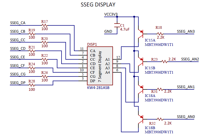
The Blackboard uses a common anode display, which means all of the anode connections for a given digit are tied together as a common circuit node. To illuminate a given segment in a given digit, a high voltage must be applied to the digit’s anode and a low voltage to the segment’s cathodes.

When working with Blackboard boards, the 4 anodes corresponding to the 4 digits are controlled by 4 transistors while the cathodes are connected to the FPGA directly. The transistors function like a voltage controlled switch. The ones used on Blackboard are PNP Bipolar transistors which act like closed switches when a low voltage is applied to the signal AN0, AN1, AN2, and AN3. Thus, they pass the 3.3V high voltage onto the actual annodes A0, A1, A2 and A3 of the seven segment device. If the cathode of a segment is 0V at the time, the current will flow throught the LED of that segment and turn it on. If the cathode of a segment is at 3.3V high voltage, then there will not be a voltage drop across the segment LED and the segment will be off.
Hint: System Diagram
Use the buttons to control the anode wires to turn the seven-segment display on and off. Figure 3 below shows the system diagram. In order to connect the switches to the system, where should you connect them?
