Electronic Components
Introduction to Circuits

Resistors
Resistors are two-terminal devices that restrict, or resist, the flow of current. The larger the value of the resistor, the less current can flow through it for any given voltage (the relationship between resistance, voltage, and current is defined by Ohm’s law, discussed later). Electrons flowing through a resistor collide with material in the resistor body, and it is these collisions that cause electrical resistance. With each collision, energy is released in the form of heat or light (as in a toaster or light bulb). Resistance is measured in Ohms, and an ohm is defined by the amount of resistance that causes 1A of current to flow from a 1V source. Resistors can be purchased in the range of less than 1 ohm to several million ohms (or megaohms).

For most circuits, a one-ohm resistance is a relatively small value, and a 100-Kohm resistance is a relatively large value. The physical size and appearance of a resistor is determined by the amount of power it must dissipate in the form of heat. Resistors that must dissipate large amounts of power (such as in a toaster) are relatively large, whereas resistors that dissipate small amounts of power (such as those used on Real Digital boards for various purposes) are relatively small. The amount of power (in Watts) dissipated in a resistor can be calculated using the equation P=I^2R (or P=VI), where I is the current flowing through the resistor, V is the voltage across the resistor, and R is the resistance. A resistor that can dissipate about 5 Watts of power would be about the size of a writing pen, and a resistor that can only dissipate 1/8 Watt is about the size of a grain of rice. If a resistor is placed in a circuit where it must dissipate more than its intended power, it will overheat and break.
Several different resistors are used on Real Digital boards. Some are used to limit LED current, and some are used on inputs (like the button and switch circuits) to both limit the current flowing to the main chip, and to help protect against electrostatic discharge (or ESD - more on this topic later). The resistors on Real Digital boards, like most resistors used in digital systems, are physically small because they will not encounter large voltages or currents. For these smaller resistors, the resistor value in Ohms is printed in microscopic numbers on the resistor body, not visible to the naked eye.
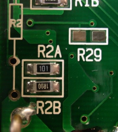
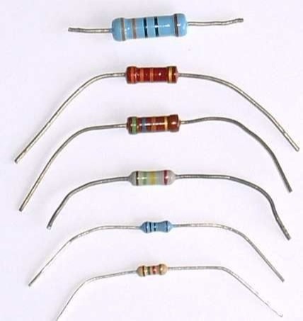
Some older or lower cost circuit boards use through hole components instead of the smaller (and cheaper) surface mount components. Through-hole resistors are about 5mm long by 2mm wide, and they are typically brown or blue, with colored stripes on their bodies (the colored stripes encode the resistance value). In circuit schematics and in parts lists, resistors are typically denoted with reference designators that begin with the letter R. You can see several rectangular white boxes with RN on the Real Digital board silk-screen. In circuit schematics, a resistor is shown as a jagged line.
Capacitors
A capacitor is a two-terminal device that can store electric energy in a self-contained electric field. Capacitors are small, local holding tanks for electric energy, and they are often used as distributed storage elements that provide instantaneous power to local circuits. The voltage across a capacitor is proportional to the amount of charge it is storing - the more charge added to a capacitor of a given size, the larger the voltage across the capacitor. It is not possible to change the amount of charge stored in a capacitor instantaneously, any more than it is possible to change the amount of water stored in a bucket instantaneously. But the more current that flows to (or from) a capacitor of a given size, the faster the voltage across the capacitor will change. The current that flows into (or out of) a capacitor in any given circuit is determined by the amount of resistance between the capacitor and the source of electric charge. The rate of voltage change on a given signal can be controlled by placing a resistor and capacitor on the signal such that the capacitor voltage can only be changed by current flowing through the resistor (and so the larger the resistor, the slower the voltage will change). This property, of limiting the rate of change on a given signal, is known as filtering. It is this property that makes capacitors useful on Real Digital boards and in many other applications.

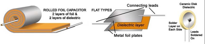
Capacitance is measured in Farads. A one Farad capacitor can store one Coulomb of charge at one volt. For engineering on a small scale (i.e., hand-held or desk-top devices), a one Farad capacitor stores far too much charge to be of general use (it would be like a car having a 1000 gallon gas tank). More useful capacitors are measured in micro-farads (uF) or pico-farads (pF). The terms “milli-farad" and “nano-farad" are rarely used. Large capacitors often have their value printed plainly on them, such as “10 uF" (for 10 microfarads). Smaller capacitors, appearing as small blocks, disks or wafers, often have their values printed on them in an encoded manner (similar to the resistor packs discussed above). For these capacitors, a three-digit number typically indicates the capacitor value in pico-farads. The first two digits provide the “base" number, and the third digit provides an exponent of 10 (so, for example, “104" printed on a capacitor indicates a capacitance value of 10x10^4 or 100000 pF). Occasionally, a capacitor will only show a two-digit number, in which case that number is simply the capacitor value in pF. (To be complete, if a capacitor shows a three-digit number and the third digit is 8 or 9, then the first two digits are multiplied by .01 and .1 respectively). Often, a single letter is appended to the capacitance value - this letter indicates the quality of the capacitor.
Capacitors are used on Real Digital boards to keep the voltage supplies and some signals stable regardless of circuit activity, and to store charge when inputs are activated in order to slow their assertion times. The majority of the capacitors on the Real Digital boards are used to “decouple" integrated circuits from the power supply. These “bypass" capacitors are placed on the board very close to the Vdd pins of all chips, where they can supply the short-term electrical current needs of the chips. Without such bypass capacitors, individual chips could cause the Vdd supply across the entire Real Digital board suddenly decrease during times of heavy current demand (this condition is often called “brown out”). Nearly every chip in every digital system uses bypass capacitors. Bypass capacitor value can be determined if the worst-case current requirements are known, but more typically, capacitors in the range 0.001uF to 0.047uF are used without regard to the actual current requirements. Real Digital boards also use bulk bypass capacitors near the power supplies and around the board to provide extra charge storage for the entire circuit board. These larger capacitors (typically 10uF to100uF) can supply the smaller individual bypass capacitors during times of exceptional need.
Depending on the size of the capacitor, the PCB silk screen will show either a circle or rectangle to indicate capacitor placement (usually, smallish capacitors are shown as rectangles, and larger capacitors as circles). Some capacitors are polarized, meaning they must be placed into the circuit board in a particular orientation (so that one terminal is never at a lower voltage than the other).
Polarized capacitors either have a dark stripe near the pin that must be kept at a higher voltage, or a dash near the pin that must be kept at a lower voltage. Silk-screen patterns for polarized capacitors will also often have a plus sign nearest the through-hole that must be kept at a relatively higher voltage. In circuit schematics and parts lists, capacitors typically use a CN reference designator.
Important Ideas
- Resistors restrict the flow of current. The larger the resistor the less current can flow through it for a given voltage. This is shown in Ohm’s law.
- Capacitors store electric energy in the form of charged particles. Capacitors allow for more stable signals regardless of fluctuation in voltage to the circuit.