Introduction and Overview
Setting up and Using the Blackboard

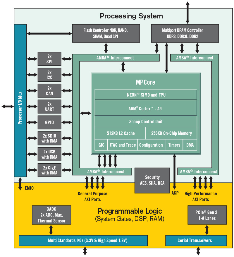
The Blackboard is a highly configurable digital design platform, designed specifically for teaching and learning hardware and software systems design. It’s based on Xilinx’s ZYNQ “System on Chip” device that includes an ARM processor, a large programmable circuit (a Field programmable Gate Array, or FPGA), and several peripheral circuits like timers and bus controllers. The figure below, reprinted from the Xilinx ZYNQ Technical Reference Manual, shows the top-level ZYNQ block diagram.
The Blackboard can be used as a stand-alone FPGA-based digital design platform, as a stand-alone ARM-based microcontroller platform, or as a combined digital system that can host custom hardware and software designs.
The Blackboard surrounds the ZYNQ chip with several peripheral devices, including a large memory array, basic I/O devices like buttons, switches, and LEDs, and more advanced devices like an accelerometer, MEMs microphone, and an HDMI port. Some peripheral devices are accessed directly from the processing system (PS), and these are always available to the ARM. Some peripheral devices are connected to the FPGA, and the FPGA must be configured with “custom IP” circuits before these can be accessed (Real Digital provides an FPGA programming file that includes all needed custom IP circuits). All peripheral circuits, whether located in the PS or FPGA, are connected to the ARM by the AMBA bus. They all appear as memory-mapped registers in the 4GByte ARM address space, so software can access them with simple load and store instructions.

Xilinx’s Vivado Webpack software can be used to design logic circuits for the FPGA, and SDK tool can be used to create software for the ARM system. Vivado supports Verilog and VHDL, and includes capture, simulation, synthesis, and FPGA programming/debugging. The SDK tool supports Assembly and C programming, and ARM programming and debugging. Both tools can be freely downloaded, and both are supported with a large collection of tutorials and reference designs. A complete Linux port is also available from Real Digital, allowing the Blackboard to host higher level embedded applications.

Real Digital’s “Digital Logic” course uses the ZYNQ’s FPGA together with Verilog/VHDL and Vivado to create a stand-alone FPGA development system; the “Microprocessors” course uses ZYNQ’s processing system with Assembly/C and SDK to create a complete, stand-alone ARM-based microprocessor system; and the digital systems (and other) courses use the both FPGA and ARM to create richer and more complex systems.
When the ZYNQ device is first powered on, a built-in “boot loader” will automatically configure the FPGA if any configuration files are found in the QSPI ROM, and it will automatically execute any ARM software found in the ROM or on an SD card. If none of these are present, the device simply waits for commands arriving from the JTAG port. When using the Vivado environment, the Blackboard is seen as an Artix FPGA system, and the ARM plays no role - FPGA configurations can be downloaded to the board, and all FPGA features and pin connections are available. When using the SDK environment, the Blackboard is seen as an ARM system, and the FPGA plays an optional role – if the FPGA has been configured with circuits that have an AXI port interface, then the ARM can interact with them (but if no such circuits are present in the FPGA, then it has no effect on the ARM system).
Accessing Peripheral Circuits
All peripheral circuits are configured, controlled, and accessed through dedicated registers that appear in the ARM memory map at preset locations. Some peripheral circuits, like the SPI controller and seven-segment controller, drive external devices. Some others have no external connections and instead add internal features like timers and interrupt controllers.
PS peripheral circuits are assigned addresses in the upper quarter of the address map, at address above C000 0000. Their address are fixed by Xilinx and cannot be changed. Many of the PS peripherals (particularly the ones used in Real Digital design projects) are described in reference documents posted on this page; more extensive documentation for all PS peripherals can be found in the ZYNQ Technical Reference Manual (TRM).
PL peripherals use address in the middle half of the address map, ranging from addresses 0x40000000 to 0xBFFFFFFF. Addresses in that range are assigned to “AXI” ports that offer high-speed connections into the FPGA (an AXI port is a subset of the AMBA bus specifically designed to connect to peripheral circuits). Real Digital has produced an FPGA configuration file (“Blackboard_standard_configuration”) to configure the FPGA with circuits that allow the ARM to access PL-connected peripheral devices. These circuits are documented in the reference materials posted on this web page. The source files are also posted so that users can modify them as desired (the Digital Systems course deals with creating custom IP blocks).
Setting up the Blackboard
To setup the Blackboard for use, power must be applied, a programming cable must be attached, and jumper blocks must be placed in the correct position (a “jumper” is a small, removable connector that can create a connection between adjacent pins - it’s the same as a switch, but it’s smaller, cheaper, and less likely to be accidently moved from one position to another).
Power
Power is provided to the Blackboard through either one of two micro-USB connectors. The primary connector (A) provides power, and also a USB port for JTAG programming and UART communications. The primary USB port is labeled “PROG UART” on Blackboard’s silkscreen. In most cases, this is the only connection needed.
Some USB ports only provide 500mA of current, which is insufficient in certain conditions (for example when driving servo motors, or when sending data via WIFI). If the board uses too much current and “browns out”, or resets itself during periods of higher current use, then the secondary USB port (C ) can be used. This port, labelled EXTP on Blackboard’s silkscreen, can provide up to 15W of power from a separate “wall wart” USB power supply. Only the 5V power signal is used from this connector – no USB data signals are available. Whichever USB connector is used, the power switch (B) will turn the board on or off.

Overall power consumption is dependent on the board’s configuration. Most designs, and especially the Real Digital design projects, will draw no more than 500mA. The ZYNQ processing system uses about 350mA, and the FPGA can consume an additional 300+mA depending on configuration. Peripheral devices can require significant current as well: if all LEDs are all illuminated, up to 150mA can be needed; servo motors can each draw 300+mA; WIFI up to 150mA; and some Pmods can draw upwards of 50mA each.
Jumper blocks
The Blackboard includes three jumper blocks (see the yellow boxes above) that can be used to select certain features. Jumper JP3 selects the board power source (either the main USB port or the accessory power port); jumper JP2 selects the default programming mode, and jumper JP1 selects the power source for the servo motors (either the main board supply, or an external supply connected to the jumper with its own cable).

Programming
The ZYNQ device on the Blackboard can be programmed from within the Vivado tool (for FPGA projects), and/or from the SDK tool (for software projects). See Real Digital’s Project 1 in the Digital Logic course for step by step instructions on using Vivado to create and download a simple Verilog project; see Project 1 in the Microprocessors course for instructions on using SDK to create and download an assembly or C project.
Programming ZYNQ’s FPGA involves writing a “.bit” file to the FPGA to configure its internal programmable elements. Bit files are produced by Vivado by synthesizing VHDL or Verilog source files. Bit files can be transferred directly to the FPGA using the “JTAG” port on the ZYNQ device, or they can be programmed into the on-board QSPI ROM so that the FPGA can be automatically configured at the next power cycle (or reset cycle). Whether arriving from the PC or QSPI ROM, bit file data is written into programmable elements dispersed across the FPGA to configure the hardware into a circuit as defined by the VHDL or Verilog source files.
Programming the ARM involves writing a “.elf” file to the ARM system. Elf files are produced by the SDK tool. They can be directly transferred to ARM’s main memory for execution, or they can be programmed into a ROM so they can be automatically loaded at the next power or reset cycle. Elf files define all the information the ARM needs to run an application program, including the compiled code and information on where it should be loaded. During the startup/boot process that occurs at power-on (or after the reset button is pressed), a special “boot loader” circuit on ZYNQ reads the .elf file and configures ZYNQ as directed.
Jumper JP2 can configure the Blackboard to automatically load programming and configuration data from an SD card, from the on-board QSPI ROM, or from a USB-connected PC using the JTAG port. When using the Blackboard for Real Digital’s design projects, it is typical to place JP2 on the “JTAG” setting.