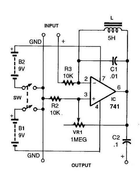
Physical Circuits
Physical circuits are constructed of real, physical devices. Smaller physical circuits (like those typically encountered in digital design) can be built on the desktop using discrete components and breadboards (or solder-ready perfboards). After a circuit has been built, it can be inspected, tested, challenged, investigated and modified as desired. But building even a simple circuit can be time consuming and frustrating. All the exact components must be located, wires and/or soldering equipment must be available, any needed safety precautions must be taken, etc.
Much can be learned from a real, physical circuit. A real circuit consumes and dissipates electric power, and often unanticipated behaviors emerge when power and signals move around a circuit. When a circuit begins to function as intended, test and measurement devices (like voltmeters or oscilloscopes) can be used to examine voltages and currents at various nodes, and those measurements can shed light on exactly how the circuit is behaving. If a circuit has been designed to perform a particular task, that performance can be verified under various challenges like temperature or voltage fluctuations.
But physical circuits can also contain design flaws that can damage components, or even create health hazards or damage to the environment. And even small circuits take time and money to build, and they can take a very long time to perfect.
In the end, any real, useful circuit must be physically built and verified. But during the design process, it is more efficient to construct a virtual, computerized model of the circuit first, before constructing a physical circuit. A circuit model can be studied, simulated, and tested more easily and more thoroughly than a physical circuit. When a simulation reveals incorrect or unexpected behavior, the circuit model can easily be modified and resimulated, much more easily than a physical circuit could be disassembled and rebuilt. It does take a small amount of extra work to build the computer model, but it is always worth it.
Model Circuits
Circuit models are built using a computer-aided design tool (or CAD tool). Structural CAD tools allow circuits to be assembled from smaller components, either using a picture-based format as shown in the drawing, or a text-based format where components and signals are given unique names, and a list identifies which signals are connected to which components. Behavioral CAD tools allow users to define a circuit’s input and output signals, and then create written description how inputs should change in response to the inputs. When creating behavioral design descriptions, another tool called a synthesizer is required to translate the behavioral description into a structural form so the circuit can be implemented.

A structural circuit description is something like a blueprint – it describes all the parts used in a circuit, and exactly how the parts are to be interconnected. Before a circuit model can be used as a blueprint to build a physical circuit, a structural description must be created. Often, engineers create structural models as a normal part of the design process, in the form of a circuit schematic. A circuit schematic shows all components in the circuit, all power supply connections, and all signals that carry information between the components. Analog circuits models are most typically designed using schematic methods (whereas digital circuits are most typically designed using behavioral methods – more on this later).
A schematic can be drawn, analyzed, debated, re-drawn, and iterated as many times as needed before a physical circuit is built. Most schematics are designed using a CAD tool. Most CAD tools can simulate circuits using an analog/SPICE simulator that accurately models and tracks voltages and currents at every single circuit node, or using an event-driven/digital simulator that only tracks whether a circuit node is currently at a logic 0 or 1. Simulating a detailed circuit model before actually constructing it is hugely beneficial. It could well be argued that circuit simulators represent the most useful and powerful computer applications so far.
Constructing and simulating a computer-based circuit model before building a physical circuit is a time-tested and proven design method. CAD models can be created quickly and easily, they can be examined intensively, and they can greatly reduce the cost, risk, and time needed to build a physical circuit. But it is important to remember that a circuit model is not a real circuit; it is only a model. And the model is only as good as the assumptions used by the programmers who wrote the CAD tool, and the designer who used the CAD tool. In rare cases, the simulated behavior in a circuit model might not exactly match the behavior observed in a physical circuit. It is always up to the engineer to validate that simulated behavior matches observed behavior (and it usually does).
Since about 2005, most digital designs use behavioral design methods based on a “hardware definition language” such as Verilog or VHDL (collectively called HDLs). In this course, we will use the Verilog language to describe circuits ranging from the simplest logic functions to complex digital systems. The Verilog language, the simulator and synthesizer, and the overall CAD environment will be introduced in stages over the first several design projects.
Important Ideas
- Physical circuits can be inspected, tested, and modified. They consume electric power when energized, and they can function properly and do some meaningful work, or they can malfunction and create serious hazards to health and property.
- Once computers became available, it didn’t take engineers long to realize that if a circuit schematic could be “captured†in a computer program, it could be simulated to any degree of accuracy before it was constructed.
