Basic Digital I/O: Slide Switch, Push Button and LED
Introduction to Circuits

Basic Input Devices: Slide Switch and Push Button
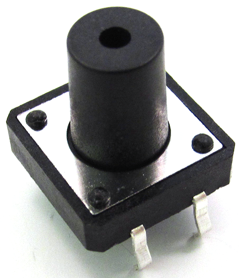
Circuits often require inputs that come directly from users (as opposed to inputs that come from other devices). User-input devices can take many forms, among them keyboards (as on a PC), buttons (as on a calculator or telephone), rotary dials, switches and levers, etc. Real Digital® boards include several input devices, typically including push buttons and slide-switches. Since digital circuits operate with two voltage levels (LHV or Vdd, and LLV or GND), input devices like buttons and switches should be able to produce both of these voltages based on some user action. The slide switches are also known as single throw-double pole (STDP) switches, because only one switch (or throw) exists, but two positions (or poles) are available (a pole is an electrical contact to which the switch can make contact). These switches can be set to output either Vdd (when the actuator is closest to the board’s edge) or GND.
The push button switches are also known as “momentary” contact buttons, because they only make contact while they are actively being pressed—they output a GND at rest, and a Vdd only when they are being pressed. Figures 2 and 3 show typical slide switch and push button circuits, respectively, used on Real Digital boards.


Basic Output Devices: LED
Circuits often require output devices to communicate their state to a user. Examples of electronic output devices include computer monitors, LCD alphanumeric panels (as on a calculator), small lamps or light-emitting diodes (LED’s), etc. Real Digital boards include different output devices, but all of them include some number of individual LED’s, and seven-segment LED displays that can display the digits 0-9 in each digit position (each segment in the seven-segment display contains a single LED). LED’s are two-terminal semiconductor devices that conduct current in only one direction (from the anode to the cathode). The small LED chips are secured inside a plastic housing, and they emit light at a given frequency (RED, YELLOW, etc.) when a small electric current (typically 10mA to 25mA) flows through them.
Individual LED’s are denoted with an “LD__” reference designator on Real Digital® boards, and seven-segment displays are denoted with a “DSP” reference designator. Individual LEDs are typically driven directly from a Xilinx® chip on Real Digital® boards, but LED displays may require the use of an external transistor to supply higher currents to the digits. Typical LED circuits on Real Digital boards are shown in Fig. 4 below.


LEDs will not turn on unless their anodes are some minimal voltage above their cathodes—typically about two volts. If less than the minimum threshold voltage is applied to an LED, it will remain dark. In the example shown below, the LED requires a 2V drop to turn on, leaving 1.3V to drop across the resistor. Thus, a 130 ohm resistor is required to cause 10mA of current to flow in the circuit (
Important Ideas
- Switches and Push Buttons are commonly used as input devices for digital system. The output of the circuit can be changed between Vdd and Gnd by pressing/releasing the push button or sliding the switch. However the correspondence between output voltage and button press/release or switch sliding is determined by actual circuit configuration.
- LED is commonly used as a simple Digital output device. Usually on Real Digital Boards, a high voltage will light it up and a low voltage will shut it down.