Vivado IP Integrator

Vivado IP Integrator
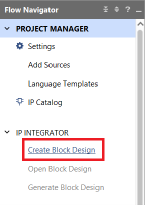
Instead of manually writing our wrapper module, we can leverage Vivado’s built-in IP Integrator to generate one automatically. Once you have created and tested the mux and demux modules, click Create Block Design to begin.
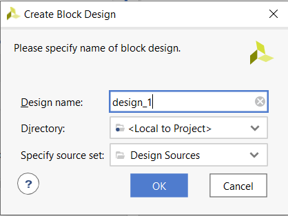
You can leave the default settings and press OK.
After a few seconds, Vivado should look open in the Block Design view. From this screen, we can add our own modules, Xilinx IP blocks, or third-party IP blocks into the block design window. We want to add our mux and demux modules, so click the Sources tab in the editor window as shown.
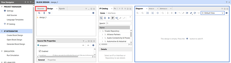
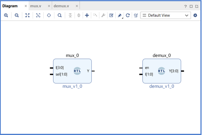
The sources window will appear on the left. Drag and drop the mux and demux modules from the sources window into the Diagram Window on the right. Alternatively, right-click on a module and select Add Module to Block Design from the drop-down menu. Your Diagram Window should look like this:
First, we will handle the external connections. Right-click on each port (the black pin) and select Make External. Alternatively, select the appropriate port and press Ctrl+T.
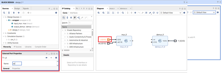
Change the name of the external ports to match your XDC file. You can do this by selecting the port name, navigating to the External Port Properties window, typing in a new name, and pressing enter. Alternatively, select the port and press Ctrl+E, type in a new name and press enter.
Now, we can connect the rest of the pins. Click and drag from an unused port to another pin or wire to connect the two together. When you are finished, it should look as follows. Tip: press the Regenerate Layout button redraw the block diagram.
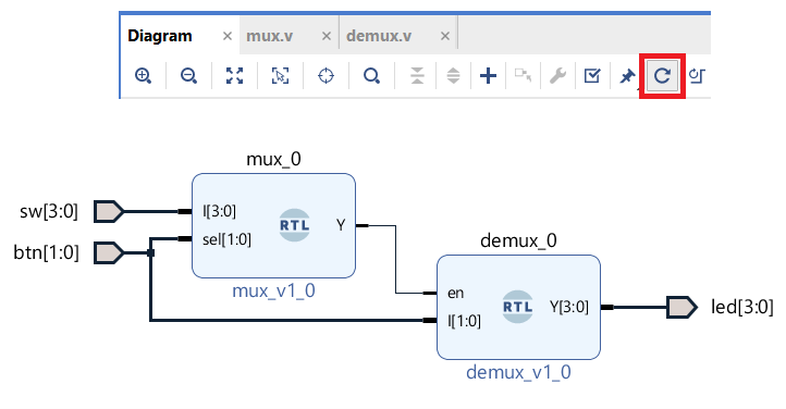
Notice that buses are shown in bold, while single wires are shown with a thin black line. Quickly check that all ports are connected, and that the bus widths match. You may find the Constant, Split, and Concat Vivado IP blocks useful for later designs.
Tip: be sure to save your block design periodically as you work with Ctrl+S. This will save lots of future headaches.
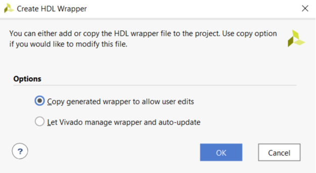
Now that the block design in complete it is time to generate the wrapper file. Navigate to the Sources window, right-click on design_1, and press Create HDL Wrapper. A pop-up will appear. You can either leave the default settings or allow user edits. Press OK.
A design_1_wrapper should appear in your Sources window. If you followed the previous tutorial in the same project, you may already have another wrapper file, as shown below.
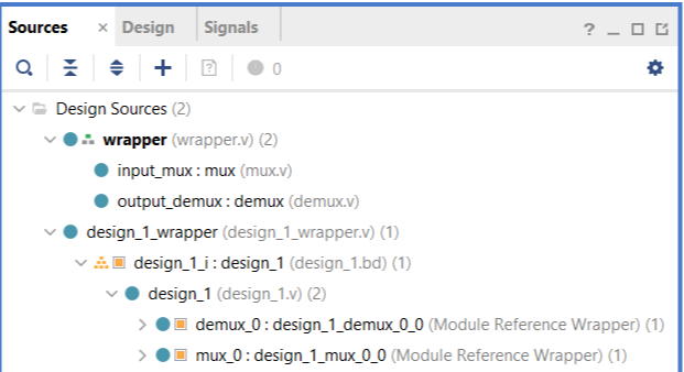
When you press Generate Bitstream the tools will only target the Top-Level Module. Currently, the Top-Level Module is wrapper (wrapper.v), as shown with the three-blocks icon. To create a bitstream for our new block design, right-click on design_1_wrapper and select Set As Top. The Sources window will update and design_1_wrapper will be the new Top-Level Module.

Finally, press Generate Bitstream, and upload the bitstream to the Blackboard to verify its operation.
Best Practices
The IP Integrator is a great tool for visualizing complex designs, but it is not a replacement for creating simple wrapper files. Often, many smaller wrapper modules are created throughout a design, and creating a block design for each small system takes too much time.
It is best practice to sketch a rough block design on paper before you start each project, design and simulate each module individually, and then connect the modules manually using wrapper files. Only when you begin using Xilinx and third-party IP blocks does the IP integrator become a time-saving tool.
More information about the IP Integrator can be found on Xilinx’s website.