Clocking Wizard
Setting up Clocking Wizard IP

Clock Wizard IP
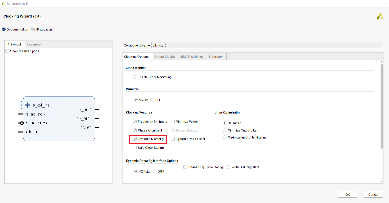
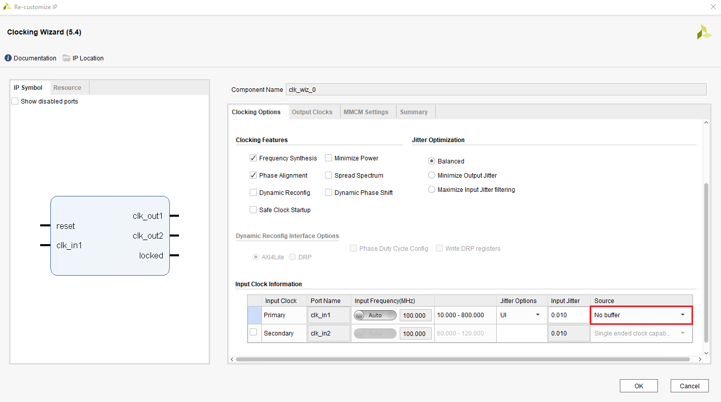
To generate different clock frequencies, you will need to use mixed-mode clock management (MMCM) units in the Xilinx FPGA. In your block design, add IP Clocking Wizard. Double click the Clocking Wizard instances you added in your block design to open up the configuration dialog. By default, it will use MMCM resource to synthesize the clock frequency you want. On the input page, if you are using AXI clock as the primary input source of MMCM, you need to select No Buffer under Source Column of Input Clock Information table, as it is already buffered. If the primary clock comes from external pin, then you need to select proper option in the Source column. You can also select Dynamic Reconfig and connect the AXI-Lite bus of the IP to the PS, so that ARM processor can write to the registers of the clock wizard IP and change the clock frequency while the system is running. This functionality is useful if you want to allow user to change display resolution at run time. You can refer to Clocking Wizard Product Guide for more information
On the output tab, you can enable up to 8 output clocks with requested frequency. Due to the implementation in the chip, you may not get the exact frequency you requested. The tool will find the closest frequencies it can get to your requests. In the figure below, two clock outputs are enabled and configured to 148.5MHz and 742.5MHz.
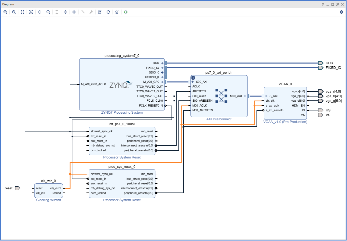
When you are using custom AXI4-Lite IP with two different clock signals (AXI clk and pixel clk) that aren’t asynchronous, you may end up with critical timing violations depending on how you’ve set up your Verilog code within your AXI4-Lite custom IP. Thus, it is important to create appropriate connections with the AXI interface, processing system, and clocking wizard. A block design example of how clocking wizard should be connected to the rest of the system is provided in figure 3.
Dynamic Reconfiugration of Clock Wizard
The Clock Wizard IP block is reconfigurable at runtime. If this option is selected when configuring the IP in vivado, an AXI interface becomes availible. This can be connected to the Zynq PS to be controlled through software. Register definitions and instructions on how to use the clock wizard through software can be found through Xilinx’s IP user guide for the Clock Wizard.