UARTs and Serial Ports

UART
A “UART" (Universal Asynchronous Receiver Transmitter) is a device/IP block that is used for asynchronous serial data communication. UARTs are called “asynchronous" because no timing signal is used as a part of the communication system‚ only the data signal is passed between devices. The receiver side must know the bit-clock frequency used by the transmitter, or it must process the received data signal and extract the bit-clock frequency on the fly.
UARTs have been used for more than 60 years, and they were the primary means of moving serial data between digital systems for most of those years, (in fact the terms UART and serial port assumed a common meaning for many years). The term UART actually refers only to the digital send and receive circuit blocks, and not the transmission system itself. The UART circuit blocks are independent from (and are probably not aware of) the physical signaling method used to transport data.
Some UART communication systems use “logic levels", or the native I/O voltage used by the UART’s host ICs, to move data around a given circuit board; others may use higher voltage “line buffers" to move data over external serial cables. For example, the serial port that was commonly found on PCs until quite recently used the “RS-232" standard to send serial/UART data at a higher voltage over cables to external devices like modems or printers.
UARTs use one signal to transmit data, and a second independent signal to receive data. A given UART may use just one signal for unidirectional “simplex" communication, or two signals for bidirectional communications. Bidirectional communications can be “full-duplex", with information flowing in both directions simultaneously, or “half-duplex", where information only flows in one direction at a time.

A UART communication system requires two UART devices, one on the transmit side, and one on the receive side. The UART may be a separate chip, but it is more likely to be an IP block that is captured as a peripheral circuit in another, larger IC (like a processor). UARTs are somewhat unique among serial busses in that they use just a data signal, without a timing signal or clock. Both the transmitter and receiver must agree on the data rate so that the receiver can decide when to “sample” the signal to record a given bit. In a typical system where data frequencies have not been prearranged and are unknown, the transmitter starts sending data at a relatively low data rate, and the receiver measures the edge-to-edge bit times as accurately possible. Once the approximate timing is established, the receiver can get initial “setup” data from the transmitter, and that typically includes the “baud rate” at which the transmitter will operate (“baud” is an older term that defines the number of symbol changes per second in a communication system; in a digital system where the symbols are either 1 or 0, baud rate is the same as “bits per second”). After the transmitter defines the intended data frequency, reliable communications can commence. But since the transmitter and receiver do not share a common time base, the receiver typically measures edge-to-edge bit times continuously so that minor on-the-fly timing adjustments can be made as needed.
A typical UART transmitter is given a byte of data to be transmitted, and stores the data in a shift register. Then the bits are sent out from the shift registers, one at a time in sequence (the LSB, or bit 0 is sent first). The eight data bits are sent in a 10-bit or 12-bit packet that includes a start bit, the eight data bits, an optional parity bit, and one or two stop bits. The transmit line is inactive (or idle) between packets, and held in a “logic high” state at the system I/O voltage (typically 3.3V). The start bit is always the first bit to be sent, and it is always low to signify that data bits are on the way.

The UART receiver stores the incoming data in a shift register. The receiver uses a “sample clock” that runs at a much higher frequency than the data frequency, so it can more accurately measure bit edge-to-edge times. Because it uses a higher frequency clock, it can find the middle of each bit with good accuracy, and it reads each bit close to the middle.

As mentioned, many UART-based serial ports used higher voltage systems for more robust data transport over longer distances. The RS-232 standard (for Recommended Standard #232, dating from 1960) used voltage translation/inversion buffers to define a “1” as a -15V to -3V signal, and a “0” as a 15V to 3V signal (and so both ends of the cable needed an RS-232 voltage translator, the transmitter to translate the logic level signals to the higher voltages, and the receiver to translate the higher voltages back to logic levels). These higher voltage, ground-centered signals resulted in a more robust, less error-prone transmission system. Although RS-232 systems are typically no longer built in to newer equipment, they are nevertheless still frequently encountered in the field.
RS-232
The RS-232 standard defined nine signals for creating a fully-compliant serial port, but seven of the nine signals were defined to support modems, and they are not a part of the UART system (only RXD and TXD are required for a full-duplex system). Modems, or “modulator/demodulators” are older communications circuits that were used to drive digital data over telephone systems.
The RS-232 standard defined two modem-centric terms, DTE (for Data Terminal Equipment) and DCE (for Data Communications Equipment, originally a modem) that were used to document the original signal connections. The DTE-side of the serial port was the “master” and data source, and was most typically a computer; it used a 9-pin male connector. The DCE-side of the port was the data consumer that could be any type of peripheral equipment; it used a 9-pin female connector.
After a time, modems were no longer used, and the use of the signals were deprecated and changed. Now serial ports rarely use anything except TXD and RXD. The table below shows the original signals and their 9-pin connector assignments.

UARTs and serial communication systems are still commonly used, but it is increasingly rare to find the older, higher-voltage RS-232 serial ports. More typically, UARTs are used on circuit boards for full-duplex serial communications (for example, the WIFI module on the Blackboard communicates with the ZYNQ device using a two-wire UART port). They are also commonly used to move serial data over a USB cable (and again, the Blackboard uses a UART to move data to and from a PC over USB).
COM port
A “COM” port (communications port) is the original name given to the serial port on the early PCs around 1980, and it is still in common use today. For many years, a COM port was almost synonymous with an RS-232 serial port, but now, a COM port generally refers to a serial port that is used to move data in and out of a computing environment. Even today, COM ports typically use UARTs, but they move data using a USB cable or Bluetooth connection.
COM ports have been around for so many years because most PC’s have built-in drivers for them, they are simple and easy to use, and they are good enough for moving lower-speed, human-speed data (like key or button presses, or lower-speed data streams). Modern COM ports can run at data rates of up to several Mbits/second, which is fast enough for many control applications as well.
Over the years, as COM ports became the standard way to move serial data to and from a PC, windows-based “terminal” programs became common as well. Terminal emulators connect to a COM port, and send ASCII characters out via the UART/serial COM port and/or receive characters in from the port. Typically, the terminal program simply sends whatever you type on the keyboard directly out, and displays characters one at a time as they arrive.
SDK Terminal Application
SDK includes a built-in terminal program specifically to connect to peripheral hardware via a PC’s COM port, so no need to go download a different one (but you could!). To run the SDK terminal, click on the SDK Terminal tab in the console window of the SDK tool.
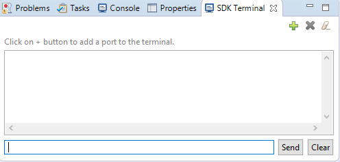
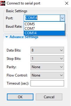
Then click on the plus sign, and use the "Connect to serial port" pop-up box to connect to a serial port and set the various fields as shown (Note: if your Blackboard is connected and powered on, you should see one or more COM port selections in the Port pull-down menu, you can select any one of them, note that all of them might not work).
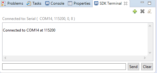
You should see a message confirming that the port connection was successful. Now, you have a direct full-duplex UART/serial communication port into the ARM. Data from the PC is sent as you type into the terminal window, and data from the ARM is displayed as it arrives.