Blackboard User Manual
Real Digital Blackboard's User Manual

General Information
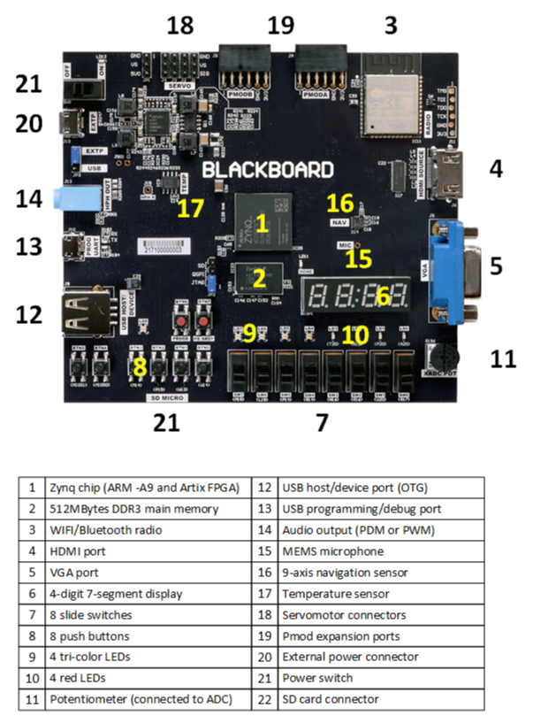
The Blackboard is a highly configurable digital design platform, designed specifically for teaching and learning hardware and software systems design. It contains an ARM processor, an FPGA, a large DDR3 memory array, several ports like WIFI, Bluetooth and USB, lots of I/O devices like an accelerometer, gyroscope, and MEMS microphone, and lots of general purpose I/O devices like buttons, switches, and LEDs.
A standard FPGA configuration makes all FPGA-connected peripheral devices available to the ARM processor via memory-mapped AXI registers, so software designs can proceed without any need to know anything about hardware design. Since most peripherals are connected directly to the FPGA, a wide assortment of interesting hardware designs can be implemented without any need to use the ARM processor. When students are familiar with hardware and software design, a virtually unlimited array of hardware/software designs can be implemented.
The Blackboard uses the free Xilinx Vivado WebPACK tool for hardware and software system design, and it contains a USB port for power, programming and debugging, so all Xilinx tools can access it directly. The Blackboard is powerful enough to run a full Linux implementation, but straight-forward enough to be used in a first-semester programming classes using C, Assembly, Verilog HDL, or VHDL. Quick overview of Blackboard features:
- A Xilinx ZYNQ XC7007S MPSoC with an ARM® Cortex-A9 processor and an Artix FPGA;
- 512Mbytes of fast DDR3 memory;
- On-board WIFI and Bluetooth (ESP-32 radio module);
- A large QSPI ROM and an SD card slot;
- Three USB ports: power & programming, additional power, and OTG/Host;
- Four servo connectors (conventional or continuous rotation);
- An on-board MEMS microphone and headphone jack;
- An on-board analog-to-digital converter;
- 12-bit analog VGA port and HDMI port;
- A 9-axis inertial module (accelerometer, gyro, and compass);
- An I2C temperature sensor;
- A large collection of buttons, switches, and LEDs;
- And two Pmod® -compatible expansion ports.
Features
1. Zynq System on a Chip (SoC)
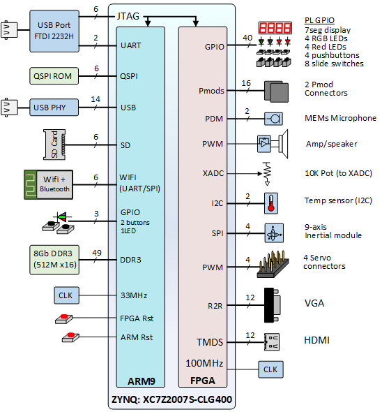
The ZYNQ XC7Z007S-1CLG400C device on the Blackboard contains a single ARM Cortex-A9 processor (based on the ARMv7-A core) and an Artix FPGA with 23,000 logic cells, 60 DSP slices, and 100 I/O pins. A wealth of information on the ZYNQ device is available from Xilinx’s Product Page.
The ZYNQ device is connected to peripherals on the Blackboard as shown in figure 2. Refer to the posted schematic and/or the posted constraints file to find the physical pin definitions. The ZYNQ runs at a maximum of 666.666 MHz, generated from the external 33.333MHz oscillator.
2. DDR3 Main Memory
The Blackboard contains a single ISSI IS46TR16256AL DDR3 memory device, organized as a 16-bit, 512Mbyte memory bank. The DDR3 device is clocked at 533.333MHz.
3. Wi-Fi/Bluetooth Radio
ESP32 is included on the Blackboard and it features 802.11b/g/n, 802.11 n (2.4GHz), up to 150Mbps Wi-Fi module. ESP32 has also a Bluetooth module that is compliant with Bluetooth v4.2 BR/EDR and BLE specifications and has many other features.
4. HDMI Port
HDMI (High-Definition Multimedia Interface) Source (J6) is directly connected to the FPGA and can be configured to send audio/video to an external device such as an LCD screen. HDMI implements the EIA/CEA-861 standards, which define video formats and waveforms.
It transfers uncompressed video data with compressed and uncompressed audio data as well. Unlike VGA where RGB are encoded as analog voltage, HDMI is a digital interface using TMDS (Transition Minimized Differential Signaling) technology that encodes uncompressed digital video data and audio data from display controller to the display monitor. Due to the nature of signal encoding, the toggling speed of the signal is usually higher than 10 times the pixel clock frequency (i.e. for 720p, if the pixel clock is 74.25MHz, the speed of HDMI signal is higher than 742.5MHz). So, on Blackboard, even though VGA port can handle 1080P, the HDMI port on Blackboard can only handle the video resolution up to 720P due to the switching speed limit of FPGA pins.
5. VGA Port
VGA stands for Video Graphics Array. VGA Port is a 15-pin DE-15 connecter and the Blackboard comes with one of these connectors. The pins are directly connected to the FPGA.
Modern VGA displays can accommodate different resolutions, and a VGA controller circuit dictates the resolution by producing timing signals to control the raster patterns. The controller must produce synchronizing pulses at 3.3V (or 5V) to set the frequency at which current flows through the deflection coils, and it must ensure that video data is applied to the electron guns at the correct time.
Video data typically comes from a video refresh memory; with one or more bytes assigned to each pixel location. The controller must index into video memory as the beams move across the display and retrieve and apply video data to the display at precisely the time the electron beam is moving across a given pixel.
A VGA controller circuit must generate the HS and VS timings signals and coordinate the delivery of video data based on the pixel clock. The pixel clock defines the time available to display one pixel of information. The VS signal defines the refresh frequency of the display, or the frequency at which all information on the display is redrawn. The minimum refresh frequency is a function of the display’s phosphor and electron beam intensity, with practical refresh frequencies falling in the 50Hz to 120Hz range. The number of lines to be displayed at a given refresh frequency defines the horizontal retrace frequency.
6. – 10. Seven-Segment Display, Switches, Buttons, LEDs
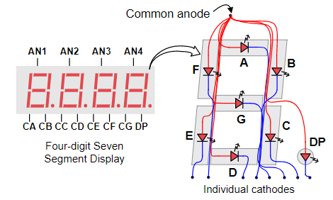
First, Blackboard has a 4-digit common anode seven-segment display module as shown in figure below, the first digit of the seven-segment display corresponds to AN1 location and the fourth digit corresponds to AN4 location.
Second, Blackboard comes with 4 pushbuttons (BTN0-BTN3) that are connected to the FPGA. Additional two push buttons (BTN4-BTN5) are controllable through MIO interface. Buttons BTN6 and BTN7 are used for reprogramming board with initial bitstream and processor reset, respectively. See the Blackboard Programmers Reference for more information on accessing the MIO interface.
Third, Blackboard has 8 slide switches that are connected to the FPGA and can be programmed to be used as inputs through hardware.
Last, Blackboard has 4 RGB (tri-color; Red, Green, Blue) LED’s and 4 regular one color LEDs that can be configured to function based on hardware design within the FPGA in the Zynq chip. Additionally, the board has an LED LD8 that is an RGB LED, which can be controlled via MIO interface.
11. Potentiometer
Blackboard has a potentiometer that can be used to control voltage level through Analog to Digital Converter.
12. – 13. USB
Hi-Speed USB 2.0 (USB3320C-EZK) Transceiver and Current-Limiting Power-Distribution Switch (NCP380HMUAJAATBG) are included on Blackboard. The USB 2.0 transceiver is connected to USB Micro B and USB A ports Blackboard as J7 and J8, respectively.
14. – 15. Microphone and Audio output
SPK0833LM4H Microphone is used on the Blackboard. The microphone can run at 1.0-3.25MHz and is directly connected to the FPGA. At every clock pulse a PDM (Pulsed Density Modulation) signal is outputted. Sequence of PDM signals can be converted into a PCM (Pulse-Code Modulation) audio sample by adding the PDM signals together over a time frame. For example, 256 samples taken at a clock frequency of 2.816MHz can be added together to create an 11kHz (2.816MHz / 256 = 11kHz) 8-bit PCM sample. The sample rate can be increased by taking more than one sample in the same time frame. This will increase the quality of the audio.
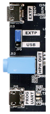
The audio can be played as a Pulse Width Modulation (PWM) signal or as a PDM signal through the on-board headphone jack (HPH OUT – J12). The audio jack Left side (HPH L) is directly connected to the FPGA). In order to play both sides (left and right on the headphone) you need to connect the HPH Right through an PMODA or PMODB to HPH R on board.
16. 9-Axis Navigation Sensor
The Blackboard contains a STMicroelectronics LSM9DS1 9-axis inertial (navigation) module. The LSM9DS1 includes a 3-axis accelerometer, a 3-axis angular rate meter (a “gyroâ€), and a 3-axis magnetic field meter (a “compassâ€). When used together, these devices can detect motion, rotation, and relative position with a high degree of accuracy. Each axis has 16-bit full scale registers, which enable the user to figure out which direction they are facing, if they are tilted, or what is the magnetic field around them. You can configure the SiP to have the following features:
- ±2/±4/±8/±16 g linear acceleration full scale
- ±4/±8/±12/±16 gauss magnetic full scale
- ±245/±500/±2000 dps angular rate full scale
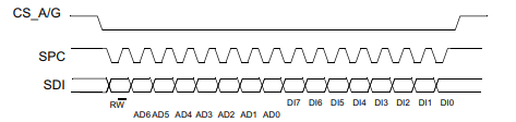
The LSM9DS1 is connected to the ZYNQ device using SPI channel 0. The SPI read is executed with 16 clock pulses (Figure 4). Also, multiple byte read command can be performed by adding 8 clock pulses. “When the CTRL_REG8 (22h) (IF_ADD_INC) bit is ‘0’ the address used to read/write data remains the same for every block. When the CTRL_REG8 (22h) (IF_ADD_INC) bit is ‘1’, the address used to read/write data is increased at every block.†LSM9DS1
- Bit 0 = 1 (READ bit)
- Bits 1-7 = address AD(6:0). Address of the register.
- Bits 8-15: data DO(7:0) (read mode). Data read from the device (Most significant bit of the byte first)
- Bits 16-…: data DO(…-8). Further data
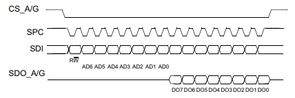
The SPI write is executed with 16 clock pulses (Figure 6). Also, multiple byte write command can be performed by adding 8 clock pulses.
- Bit 0 = 0 (WRITE bit)
- Bits 1-7 = address AD(6:0). Address of the register.
- Bits 8-15: data DO(7:0) (write mode). Data written to the sensor registers (Most significant bit of the byte first).
- Bits 16-…: data DO(…-8). Further data.
Like SPI read execution for Accelerometer/Gyroscope, the command for Magnetometer is performed with 16 clock pulses. See the Blackboard Programmers Reference for more information on accessing the LSM9DS1.
17. Temperature Sensor
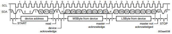
Real Digital’s Blackboard has a temperature sensor, LM75BDP, provided by NXP semiconductors that can be accessed using I2C interface on the Zynq chip. The 7-bit address for this chip is 1001000.
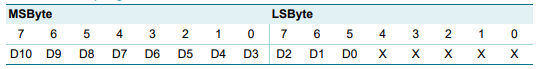
The temperature register contains two 8-bit data bytes that consists of MSByte (Most Significant Byte) and LSByte (Least Significant Byte). Figure below shows the register overview. There is a total of 11 bits of actual data. D10 – D3 is considered the integer value of temperature data, where D10 is the sign bit (D10 = 0 means positive, D10 = 1 means negative). D2-D0 are the decimal point precision of the temperature value. For example,
-
011 1111 0111 (1015 in decimal) would equal to +126.875C that can be calculated with the following equation: Temperature= +Temp Data0.125 ℃ or Temperature=10150.125℃=126.875℃
-
110 0100 1001 (-439 in decimal) would equal to =54.875C that can be calculated with the following equation: Temperature=-(Two’s Complement of Temp Data)0.125 ℃ or Temperature= -4390.125℃=-54.875℃
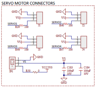
18. – 19. Servo Motor Connectors and Two Pmod® Connectors
The blackboard has a total of 4 servo motor connectors that can be powered when JP3 is set to external port. As shown in figure below, the SERVO1, SERVO2, SERVO3, and SERVO4 connectors are connected to the FPGA and the signal for servo control can be triggered from there.
Blackboard comes with two Pmod® connectors which are tied to the FPGA and be controlled through it.
20. – 21. Power
The power switch is used to turn ON/OFF the power on the board. The board can be powered through PROG UART (J10) port if jumper JP3 is connected across center pin and USB pin. Blackboard may be powered externally as well when the jumper JP3 is connected across the center pin and EXTP pin as shown in figure below.
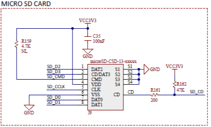
22. SD Card
The blackboard comes with a microSD-CSD-13-xxxxx Micro SD card reader as shown in figure below. This card can read a maximum of …. GB.
Programming
The Blackboard contains a built-in, USB-based programming circuit that can be driven from within the Xilinx CAD tools. Blackboard’s “hardware definition fileâ€, or.hdf, which can be used as a Hardware Platform for projects in the microprocessors course. This file contains a .bit file to configure ZYNQ’s FPGA with IP blocks that make Blackboard’s peripheral devices (like LEDs and switches) available to the processor through memory-mapped registers. Reading and writing values to/from these registers allows you to access all of the peripheral devices on the board. You are able to use the exact same .hdf file for every project. The Real Digital®’s PROGRAMMERS REFERENCE DOCUMENT for the Blackboard provides details on register addresses and functions.