Clocking Wizard
Using the Clocking Wizard to produce system clocks

Xilinx provides a number of free-to-use IP blocks that can greatly aid and accelerate various design projects, and one of the most useful is the Clock Management Tile (CMT). All of the CMTs in the FPGA (there are several) contain a mixed-mode clock manager (MMCM) that can generate a wide range of output clock signals from a single input clock. Each CMT can output up to seven independant clock signals. They can be faster or slower than in the input clock, and they can have precise phase control, good stability, and low jitter.
Vivado’s Clocking Wizard is an easy way to configure a CMT to produce any required clock signals. The Wizard lets you enter your desired clock frequencies and select a few signal properties, and then it produces a Verilog module that you can include in your design. This document illustrates using the Wizard to define a given clock output.
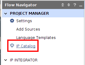
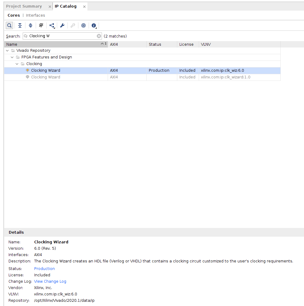
In the Project Manager/Flow Navigator window in Vivado, click on the IP Catalog to view the available IP Blocks. Expand “FPGA Features and Design” and select the Clocking Wizard from the Clocking pull-down.
Double-click on the Clocking Wizard entry to start the Wizard.
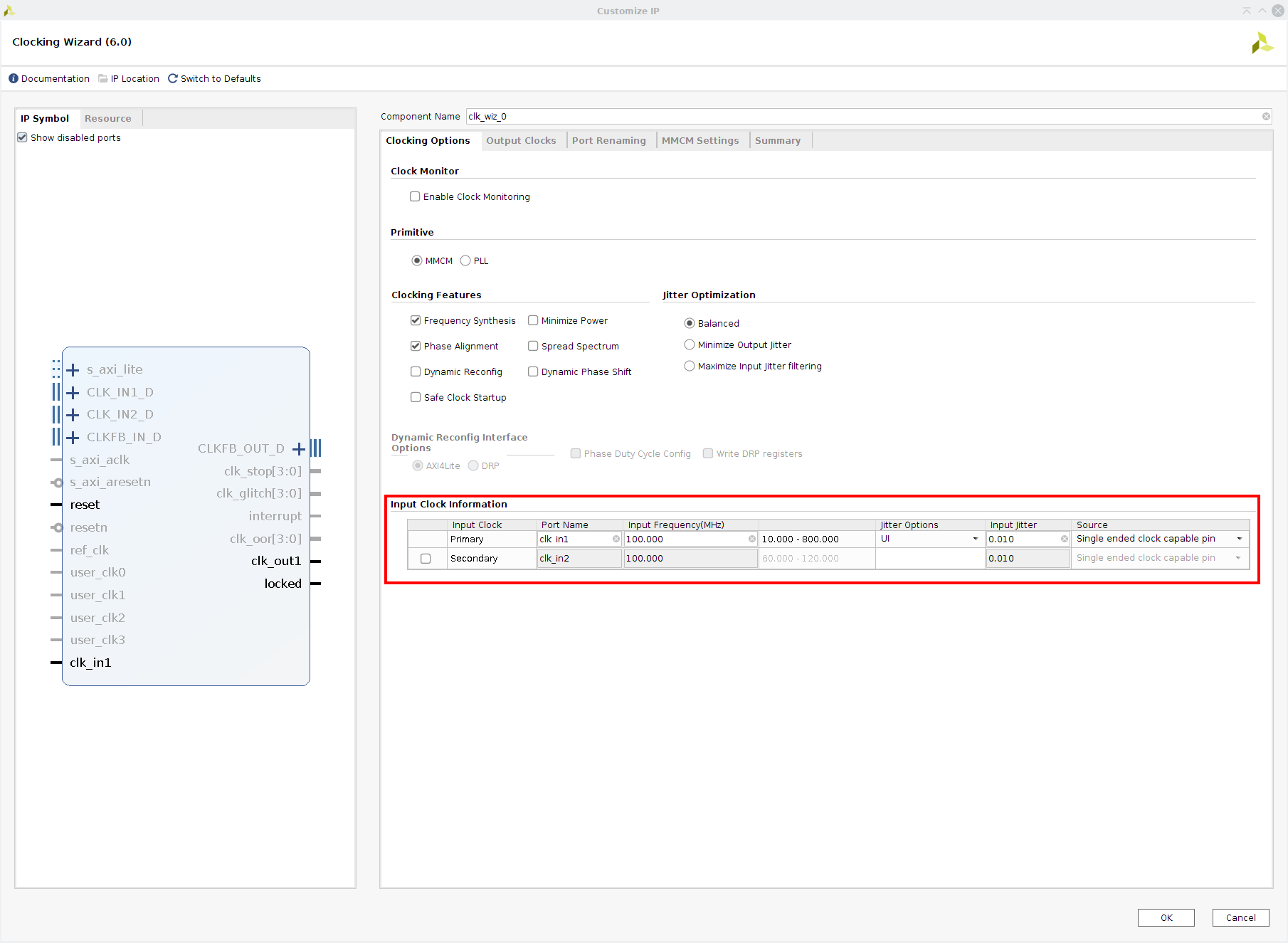
Notice there are five tabs at the top of the interface – we will enter information into the first two (Clocking Options and Output Clocks).
In the Clocking Options tab, leave the default settings for Primitive (MMCM), Clocking Features (Frequency Synthesis and Phase Alignment), and Jitter (Balanced). These settings are the most typical for most clock signals. In the Input Clock Information panel, enter your system’s input clock frequency (100MHz for Real Digital boards), and leave the defaults for Jitter (UI) and Source (Single ended clock capable pin).
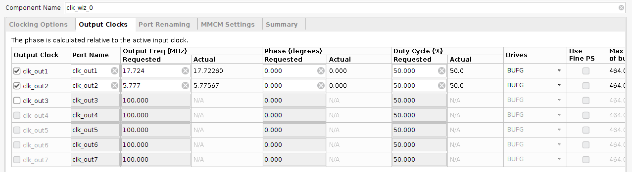
In the Output Clocks tab, you can define up to seven output clocks by entering the desired output frequencies in the “Requested” boxes under Output Freq (MHz). For a VGA controller and VGA-to-HDMI block, two clocks (25MHz and 125MHz) are needed. In the example shown, two random clocks were requested. Based on the requested target frequencies, the Wizard will produce the closest attainable output frequencies. Note that not all frequencies can be produced exactly due to the limited precision achievable when multiplying and dividing clock frequencies. If, for example, 17.724MHz was entered as shown, the “Actual” box will show 25.72260MHz – that is the closest frequency that is possible to produce. Likewise, you can enter a requested clock phase (0 means no phase delay) and duty cycle (50 means the clock waveform is high 50% of the time), and the Wizard will report the closest attainable result.
Leave the defaults for the remaining selections (Automatic Control On-Chip tells the CMT to use it’s internal resources, and enabling the reset input and locked output make the resulting Verilog module compatible with other IP blocks).
Click OK to accept the parameters you’ve entered, and then click Generate in the next window to have the Wizard generate the “output products”.
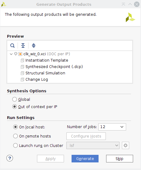
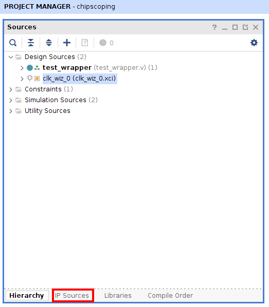
Output products include the Verilog source files, and also a template you can cut/paste into your project source file to instantiate the IP block. If you are curious, you can view the resulting code, find the instantiation of the CMT, and see the divider values (and other parameters) the Wizard populated. To view the instantiation template, select the “IP Sources” tab at the bottom of the the Sources window in the Project Manager.
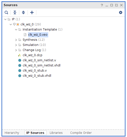
Expand the Clocking Wizard IP, and open the .veo file in the Instantiation Template directory.
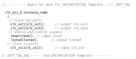
Template Verilog code you can cut and paste into your project is near the bottom of the file.
At any time, you can rerun the Wizard to make changes to the IP block.
Finally, you can instantiate the IP block in your project, just like you’d instantiate any other component (be sure the input clock you connect to the IP core matches the input clock you specified when configuring the IP core).
The IP block includes an optional reset signal, and its polarity is configurable in the Wizard. The block also includes a ‘locked’ output. The locked signal indicates the MCMM is producing a stable and reliable clock - some IP blocks check this input, and will only operate when it is asserted.
The Verilog code below provides and example of instantiating a CMT IP block produced by the clocking wizard. The code uses the template produced in the example shown above.
module count_div(
	input pin_clk,
	input rst,
	output A_out,B_out
);

	wire clk_A;
	wire clk_B;
	wire wiz_lock;

	wire [7:0] count_A, count_B;

	assign A_out = count_A > 63;

	assign B_out = count_B > 63;


	clk_wiz_0 inst_clk_wiz
	(
	// Clock out ports
	.clk_out1(clk_A),     // output clk_out1
	.clk_out2(clk_B),     // output clk_out2
	// Status and control signals
	.reset(rst), // input reset
	.locked(wiz_lock),       // output locked
	// Clock in ports
	.clk_in1(pin_clk)		//input clk_in1
	);


	//8-bit counter run by clock output 1
	counter cntA
	(
		.clk(clk_A),
		.rst(!wiz_lock),
		.en(1),
		.count(count_A)
	);

	//8-bit counter run by clock output 2
	counter cntB
	(
		.clk(clk_B),
		.rst(!wiz_lock),
		.en(1),
		.count(count_B)
	);

endmodule