Creating a Vivado Project
Using Vivado's New Project Wizard

Vivado Projects
Vivado “projects” are directory structures that contain all the files needed by a particular design. Some of these files are user-created source files that describe and constrain the design. Others are system files created by Vivado to manage the design, simulation, and implementation of projects. In a typical design, you will only be concerned with the user-created source files. You can access the system files if you need more information about your design or precise control over certain implementation details.
Creating a project in Vivado will take you through a series of dialogues. The steps include:
- Naming your project.
- Choosing a storage location.
- Selecting a project type.
- Adding and/or creating design sources and constraint files.
- Selecting which physical part you are desiging for.
Below each step is shown and explained.
Start Vivado
In Windows, you can start Vivado by clicking the shortcut on the desktop.
In Linux, you can start Vivado from a shell as shown in TUTORIAL: VIVADO TOOLS INSTALLATION.
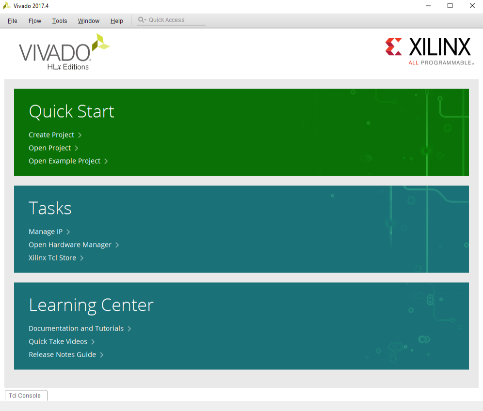
After Vivado is started, the window should look similar to the picture in figure 1.
Create a Project
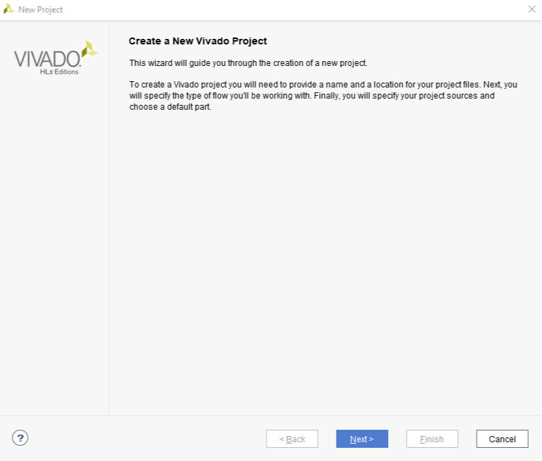
Click on “Create Project” in the Quick Start panel. This will open the New Project dialog as shown in Figure 2. Click Next to continue.
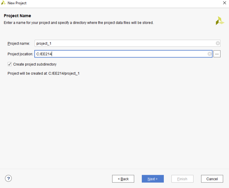
Set Project Name and Location
First, enter a name for the project. In the figure, the project name is the default: “project_1”, This isn’t a particulary useful name. It’s good practice to make the project name more descriptive, so you can identify your designs in the future. For example, if you design a seven-segment controller, you might call the project “seven_segment_controller”. For projects related to coursework, you might include the course name and project number - for example, “ee214_project2”.
You can also select a location to store your project and it’s associated files. Keeping relevant projects together will make moving/copying all relevent projects easier, should you need to.
You should avoid having spaces in the project name or location; Not all tools will handle whitespace the same and this may cause unexpected behaviour.
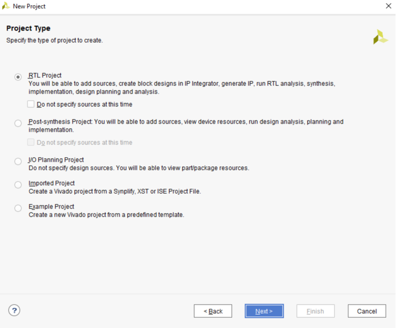
Select Project Type
The “project type” configures certain design tools and the IDE appearance based on the type of project you are intending to create. Most of the time, and for all Real Digital courses, you will choose “RTL Project” to configure the tools for the creation of a new design. RTL stands for Register Transfer Language, usually used to describe a hardware design language like Verilog.
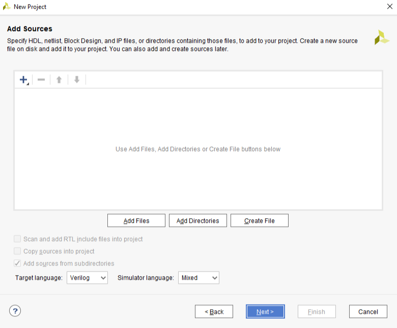
Add Existing Sources
In a typical new or early-stage design, you won’t add any existing sources because you haven’t created them yet. But as you complete more designs and build up a library of previously completed and known good designs, you may elect to add sources and them use them in a new design.
For now, there are no existing sources to add, so just click Next.
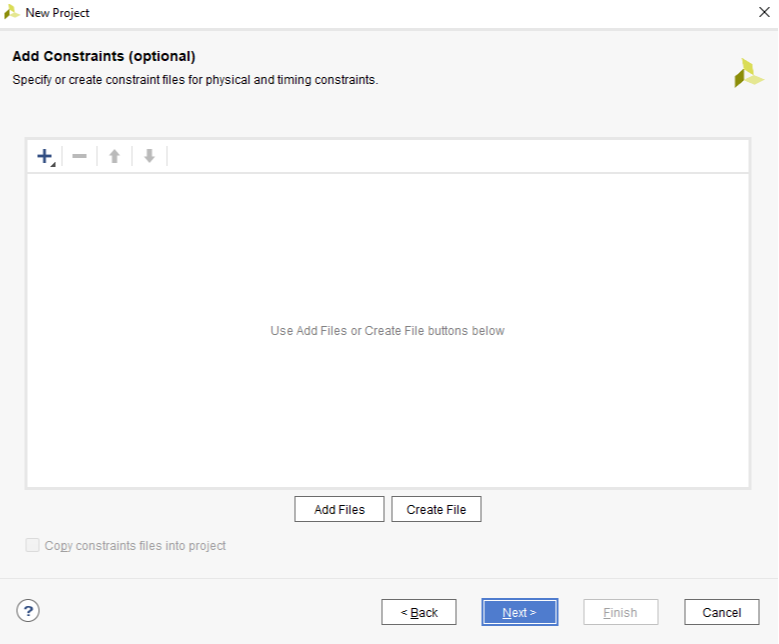
Add Constraints
Constraint files provide information about the physical implementation of the design. They are created by the user and used by the synthesizer. Constraints are parameters that specify certain details about the design. For example, some constraints identify which physical pins on the chip are to be connected to which named circuit nodes in your design. Other constraints configure various physical attributes of the chip, such as I/O pin drive strength (high or low current). Finally, some constraints identify physical locations of specific circuit components.
In a later step, you will create a constraints file to identify which named circuit nodes must be connected to which physical pins. For now, you have no existing constraints file and you can simply click next.
Xilinx Design Constraints (XDC)
The Xilinx Design Constraints (.xdc filetpye) is a file format used for describing design constraints. They can be I/O delays, clocks, timing exceptions, and physical constraints. You will need to create an .xdc file in order to synthesize your designs for the Blackboard. There are several ways to add the required information into an .xdc file. These possibilities will be explored later.
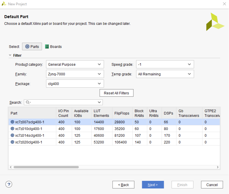
Select Parts
Xilinx produces many different parts, and the synthesizer needs to know exactly what part you are using so it can produce the correct file to program for a specific part. To specify the correct part, you need to know the device family and package, and less critically, the speed and temperature grades. The speed and temperature grades only affect special-purpose simulation results; they have no effect on the synthesizer’s ability to produce accurate circuits. The figure and table show the correct information for the Blackboard’s Xilinx part.
| Part Number | xc7z007sclg400-1 |
|---|---|
| Family | Zynq-7000 |
| Package | clg400 |
| Speed Grade | -1 |
| Temperature Grade | C |
How to find your the part on your board
You can find the details about the Zynq part from the markings on the IC, the reference manual for your board, on the webpage where you purchased the board, or in the board’s schematic.
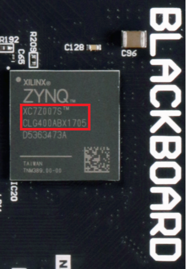
From Markings on IC
Usually, you can find the part number directly from the markings on the back of IC. In the picture below, you can see the FPGA part number on Blackboard board.
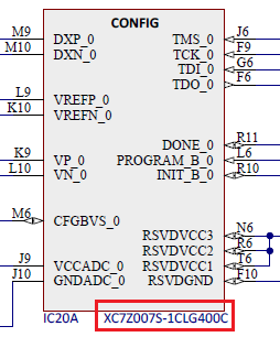
From Board Schematic
You can also find the part number from Blackboard’s schematic, as shown in the figure below. You can get the schematic for Blackboard here.
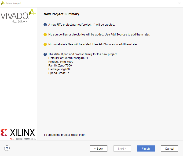
Check Project Configuration Summary
On the last page of the Create Project Wizard a summary of the project configuration is shown. Verify all the information in the summary is correct, and in particular make sure the correct FPGA part is selected. If anything is incorrect, click back and fix it. When everything looks good click Finish to finish create an empty project.
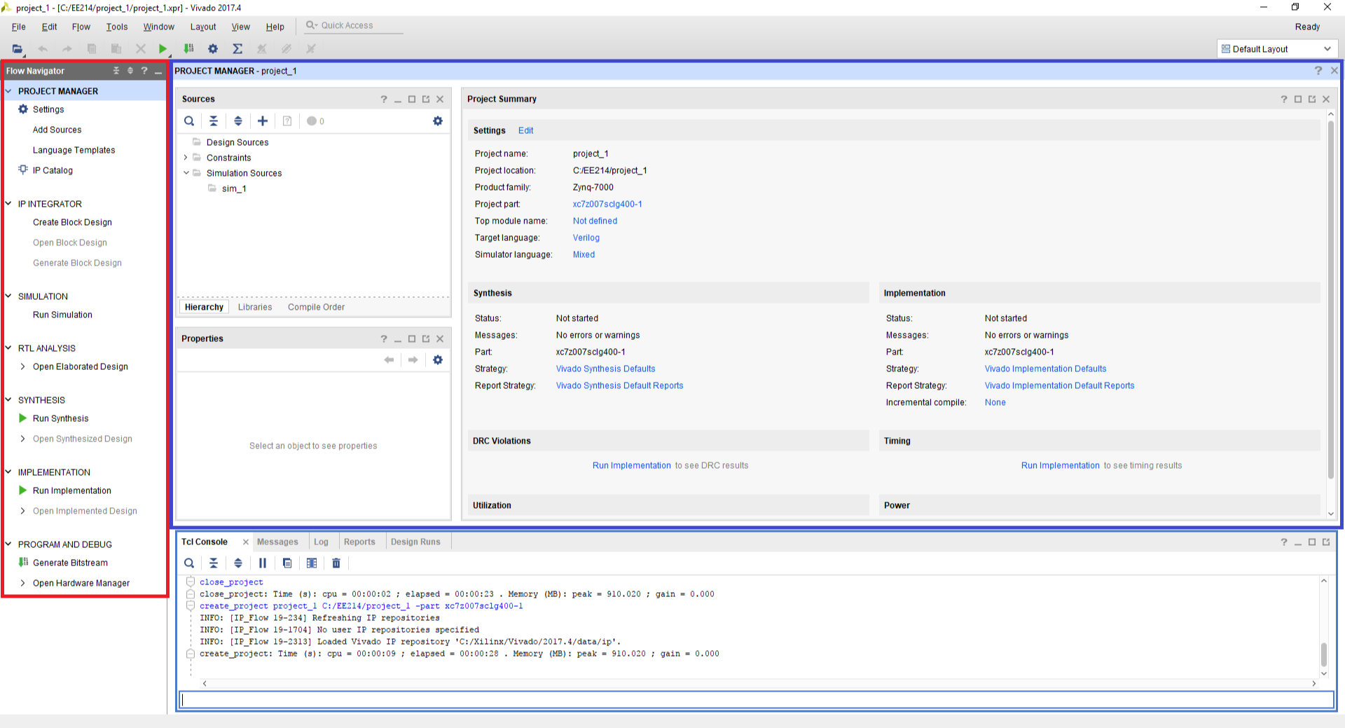
Vivado Project Window
When you complete all of the dialogues in the Create Project Wizard, you will be taken to the main Vivado Project window. This is the main “working” window where you enter and simulate your HDL code. When you’ve finished writing your code you can run synthesis and program your hardware.
Vivado provides a Flow Navigator (outlined in red, figure 11), which is found in the leftmost pane, which allows you to launch tasks.
When you first open a project, vivado will show the Project Manager (outlined with blue, in figure 11) which is used to manage your project’s files and overall settings.
The pane at the bottom contains tabs which provide access to the TCL console, Messages (syntax errors,critical warnings, etc), and a log. Various other things can be displayed here as well.
As you use Vivado you will become familiar with these view and other contexts such as the text editor, design views, block diagrams, and the simulator.