A First Look At Circuits
Introduction to Circuits

A First Look at Circuits
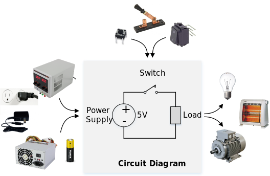
An electric circuit consists of a power supply, one or more “load” devices that consume electric power to produce some useful output like light, heat, or motion, an optional means of control (e.g., an on-off switch), and conducting wires to move electric power between the power supply and load. In an electric circuit, power must flow from the positive terminal of the power supply through one or more load devices and back to the negative terminal of the power supply, thereby forming a complete circuit. If the connections between the load and either the positive or negative terminals of a power supply are interrupted, the circuit will be broken and the load will not receive any current.

A power supply may be thought of as reservoirs of positive and negative charges that are held in close proximity, but that cannot recombine within the power supply itself. Positive and negative terminals on the supply make the charges available to an outside circuit. When these terminals are connected through an external circuit, charges flow from the reservoirs through the terminals and load and recombine within the power supply.
The charged particles available from a power supply have a potential energy equal to the amount of work done to separate them. This potential energy difference is measured in volts (or voltage). Thus, the voltage of a power supply is a measure of the “electric potential” or the “electro-motive force” that can force charge to flow through a circuit. Charge is carried by electrons, and the flow of electrons through a circuit is called electric current. The flow rate of electric current is measured in amperes, where one ampere is equal to one coulomb
A typical power supply has large amounts of charge available at a given voltage, so that large and varying amounts of current can be supplied without a change in voltage. Most power supplies for “desktop” circuits produce voltages in the range of 3.3V to about 12V, a range that is generally considered safe for humans. A typical desktop supply (or plug-in “wall wart” supply) can produce anywhere from 100mA to 5A of current at the specified voltage – enough to power most small to medium sized experimental or lab-based circuits. The voltage output by a power supply is typically shown next to the supply in a schematic.
Any load device in a circuit will present some amount of resistance to the flow of electric current (resistance in measured in Ohms). The voltage available to force current through the load, and the resistance of the load determines how much current will flow according to Ohm’s law:
Signals
Some conductive wires in a circuit transport power between the power supply and the load devices. These wires, often called “rails”, are held steady at the same voltage, and they deliver electric power to devices around the circuit as it is needed. Other conductive wires move information between devices in a circuit – these wires transport “signals”. Signals differ from rails in that they transport information, not power. They use less current, and their voltage changes over time to encode or represent new and changing information. Signals can move information from one circuit component to one other, or from one component to several others. All the conductors and components in a circuit that are connected together by a single signal are said to form a circuit node; all the components connected to any given node access the same information.

Electric Vs. Electronic Circuits
Electric circuits use power rails and simple control means (like manual switches) to drive basic load devices like lights, heaters, and motors. Electronic circuits also use electric current to power load devices, but they differ in a crucial way – the devices in an electronic circuit use and/or are controlled by electric signals instead of manual switches. Electronic devices, like transistors, amplifiers, processors, and other semiconductor-based components (we will discuss semiconductors later) consume electric power, and they also use signals to define their operating state and control their behavior. As examples, a home-wiring circuit that provides power to a light bulb based on the state of a mechanical switch is an electric circuit, whereas a button to change channels on a TV is part of an electronic circuit.
Electronic circuits are often classified as “analog” and “digital” circuits. Analog circuits use variable voltages on conductive wires to represent information in a circuit – think of a microphone that produces a voltage between
Analog circuits can suffer from poor performance if there is too much noise on their internal signals. In the microphone example, if the circuit used a
Digital circuits also uses voltage levels on conductive wires to encode and represent information, but rather than use continuously varying voltages, they use only two distinct voltage levels. All information in a digital circuit is represented by a “logic high voltage”, which is typically defined as a voltage range between about 70% and 100% of the maximum system voltage (perhaps
Since digital circuits restrict nodes to operating at one of two distinct voltages, it is common practice to associate a circuit node at a logic high voltage (or Vdd) with a ‘1’, and a circuit node at a logic low voltage (or ground) with a ‘0’. Thus, every node in a digital circuit is either at a ‘1’ or ‘0’, not counting the short amount of time it takes to transition between those states. And since all circuit nodes in a digital circuit can be associated with a ‘1’ or ‘0’, it is common to use binary numbers when describing the state of a digital circuit. Any individual wire (or node) can transport either a ‘1’ or ‘0’, and a group of wires viewed as a single logical unit can transport a binary number. For example, if 8 wires are viewed as a single logical unit (called a “bus”), then 8-bit binary numbers can be transported by that bus.

Digital circuits can represent the same information as analog circuits, but the analog information must first be converted into digital form. Any continuously varying analog signal can be represented as a sequence of discrete numbers that define the analog signal’s amplitude at a given time. The requirements of the signal that is to be “digitized” dictate how many points per second are required for an adequate representation, and how many bits per point. If, for example, a 0V to 3.3V analog signal produced by a microphone was to be “digitized” for representation in a digital circuit, the maximum frequency content that needed to be preserved in the digital representation would dictate the sample rate (in general, the sample rate is at least two times, and up to 10 times the analog frequency that must be preserved), and the required dynamic range would dictate the number of bits (dynamic range is the ratio between the smallest and largest signal amplitudes that can be represented). For regular spoken voice, about 5 KHz of analog frequencies should be preserved, with about 48dB of dynamic range, indicating a sample rate of 10 KHz or more, with at least 8 bits per sample.
In digital circuits, the Vdd and GND rails supply electric power to the circuit and define voltages for representing a ‘1’ and a ‘0’. Vdd may be thought of as the “source” of positive charges in a circuit and the source of ‘1’ information, and GND may be thought of as the “source” of negative charges in a circuit and the source of ‘0’ information. In modern digital systems, Vdd and GND are separated by anywhere from 1 to 5 volts. Older or inexpensive circuits typically use 5 volts, while newer circuits use 1-3 volts.