VGA to HDMI
Use VGA to HDMI/DVI Converter IP

Real Digital boards include HDMI connectors, but HDMI display controllers are relatively complex and difficult to design. Real Digital offers a VGA-to-HDMI conversion IP block that allows a VGA controller to drive an HDMI monitor. Any VGA-compatible controller that produces HS, VS, VDE (Video Data Enable, de-asserted to identify refresh times) and the R, G, and B color signals (up to 8 bits each) can be used.

The VGA-to-HDMI IP block needs two clock signals – a “pixel clock” to define the time that each pixel is driven into the display, and a second, faster clock (5x the pixel clock) to manage internal resources. A 640x480 VGA display (also known as a 480p display) requires a 25MHx pixel clock, and a 125MHz 5X clock. Note the 5X clock is higher frequency than the FPGA’s 100MHz clock - the FPGA’s “clock management tile” (CMT) can be used to generate all required clock signals. (Note: The CMT can use a single clock source to generate a large number of stable and accurate clock signals, both faster and slower than the input clock. The CMT can be configured and instantiated using a “wizard” to define the required frequencies – see the linked document for more information.) Clocking Wizard
The VGA-to-HDMI block also contains four auxiliary input ports. These ports can optionally be used in copy protection schemes. If they are not used (typical), they can be tied to ground.
The outputs of the VGA-to-HDMI block are tied directly to the FPGA pins that drive an external HDMI buffer. Four main HDMI signals (clock and three data signals for R, G, and B) are output, and these signals use the “transition minimized differential signals” (TMDS) I/O standard. To achieve high data rates, each signal uses two wires that are driven oppositely (complimentarily) to each other, and each signal is encoded to minimize 1-0 and 0-1 transitions. Adding the following lines to the constraints file will ensure TMDS signaling is used.
#These constraints are for the Blackboard
set_property -dict { PACKAGE_PIN U19   IOSTANDARD TMDS_33 } [get_ports HDMI_CLK_N]; #IO_L12N_T1_MRCC_34 Sch=HDMI_TX_CLK_N
set_property -dict { PACKAGE_PIN U18   IOSTANDARD TMDS_33 } [get_ports HDMI_CLK_P]; #IO_L12P_T1_MRCC_34 Sch=HDMI_TX_CLK_P

set_property -dict { PACKAGE_PIN V18   IOSTANDARD TMDS_33 } [get_ports HDMI_D_N[0]]; #IO_L21N_T3_DQS_34 Sch=HDMI_TX0_N
set_property -dict { PACKAGE_PIN P18   IOSTANDARD TMDS_33 } [get_ports HDMI_D_N[1]]; #IO_L23N_T3_34 Sch=HDMI_TX1_N
set_property -dict { PACKAGE_PIN P19   IOSTANDARD TMDS_33 } [get_ports HDMI_D_N[2]]; #IO_L13N_T2_MRCC_34 Sch=HDMI_TX2_N

set_property -dict { PACKAGE_PIN V17   IOSTANDARD TMDS_33 } [get_ports HDMI_D_P[0]]; #IO_L21P_T3_DQS_34 Sch=HDMI_TX0_P
set_property -dict { PACKAGE_PIN N17   IOSTANDARD TMDS_33 } [get_ports HDMI_D_P[1]]; #IO_L23P_T3_34 Sch=HDMI_TX1_P
set_property -dict { PACKAGE_PIN N18   IOSTANDARD TMDS_33 } [get_ports HDMI_D_P[2]]; #IO_L13P_T2_MRCC_34 Sch=HDMI_TX2_P
Using the VGA-to-HDMI IP Core
First, download and unzip the VGA-to-HDMI IP core: HDMI/DVI IP Core 2020
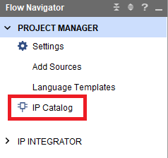
Next, open the IP Catalog in Vivado’s Flow Navigator.
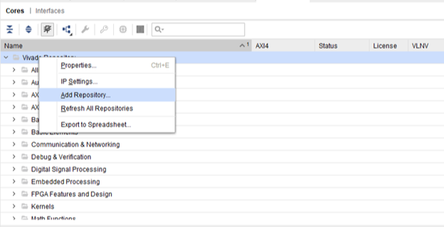
Right click on “Add Repository”, and select the downloaded/unzipped folder that contains the IP core. This will place the core in the User repository.
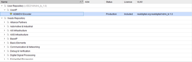
You will see that the core was added in the User Repository.
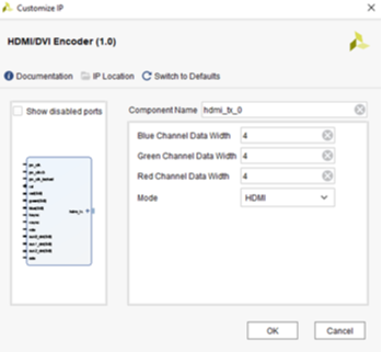
Double-click on the IP core to bring up the customization box.
Select the number of bits per color signal you will use (between 1 and 8), and select HDMI mode. Click OK to confirm your selections.
Finally, click generate in the next dialogue box to create the IP block’s output products. Output products include the Verilog source files, and also a template you can cut/paste into your project source file to instantiate the IP block. If you are curious, you can view the resulting source code, and see how everything is defined and connected.
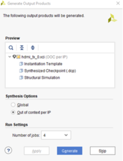
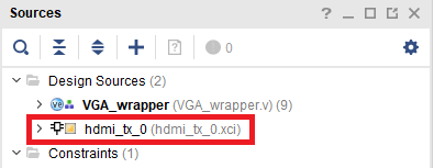
The IP Core will appear the Project Manager sources tab (you can always change any settings by double-clicking the IP core icon). Note there are four tabs at the botto of the Sources window in the Project Navigator. Click on the “IP sources” tab to view the IP core output products. If you expand the IP core, you will find a Verilog instantiation template that you can cut and paste into your top-level source file.
The code below is taken from the instantiation template (with some white space removed) to provide an example of instantiating the VGA-to-HDMI IP core (instantiation statements for the CMT and VGA IP blocks are also included). You can create higher resolution displays using the following pixel clock frequencies.
- 640 x 480 at 60Hz: 25MHz;
- 800 x 600 at 60Hz: 40MHz;
- 1024 x 768 at 60Hz: 65MHz;
- 1280 x 720 at 60Hz (720p): 74.25MHz.
`timescale 1ns / 1ps

module vga_wrapper(
	input clk,
	input rst,
	output hdmi_clk_n,
	output hdmi_clk_p,
	output [2:0] hdmi_tx_n,
	output [2:0] hdmi_tx_p,
);

	wire clk_25MHz, clk_125MHz;
	wire locked;
	wire hsync, vsync, vde;
	wire [7:0] red, green, blue;
	wire [9:0] x_pix, y_pix;

	//clock wizard configured with a 1x and 5x clock
	clk_wiz_0 clk_wiz (
		.clk_out1(clk_25MHz),
		.clk_out2(clk_125MHz),
		.reset(rst),
		.locked(locked),
		.clk_in1(clk)
	);


	//VGA Sync signal generator
	vga_sync vga (
		.clk(clk_25MHz),
		.rst(rst),
		.hsync(hsync),
		.vsync(vsync),
		.video_active(vde),
		.px(x_pix),
		.py(y_pix)
	);


	//Real Digital VGA to HDMI converter
	hdmi_tx_0 vga_to_hdmi (
		//Clocking and Reset
		.pix_clk(clk_25MHz),
		.pix_clkx5(clk_125MHz),
		.pix_clk_locked(locked),
		//Reset is active HIGH
		.rst(rst),

		//Color and Sync Signals
		.red(red),
		.green(green),
		.blue(blue),
		.hsync(hsync),
		.vsync(vsync),
		.vde(vde),

		//aux Data (unused)
		.aux0_din(4'b0),
		.aux1_din(4'b0),
		.aux2_din(4'b0),
		.ade(1'b0),

		//Differential outputs
		.TMDS_CLK_P(hdmi_clk_p),
		.TMDS_CLK_N(hdmi_clk_n),
		.TMDS_DATA_P(hdmi_tx_p),
		.TMDS_DATA_N(hdmi_tx_n)
	);

endmodule