Project 7 Working with Servomotors
Configuring a PWM signal to drive a servomotor

Introduction
In this project, you will control servomotors (or just “servos”) from the Blackboard. Servos are low-cost, commonly-used motors that include a gearbox and a controller. They are typically high torgque, and offer relatively precise control over their position and motion. Servos can only rotate over a limited range of perhaps 180 to 270 degrees, and when they are directed to rotate to a given position, they actively hold that position, working against external forces that might try to move them.
As an example, consider a servo motor used to steer a 4-wheel RC vehicle. Once the front wheels are rotated to a given angle, that angle should be maintained even as the vehicle encounters obstacles (like hitting rocks or other debris) that apply a force to change the steering angle.
A standard servo motor control signal is a PWM signal with particlar timing characteristics. This project will use the Triple Timer Counter (TTC) module to generate a suitable PWM.
Before you begin, you should:
- Have a basic understanding of PWM signals;
- Know how to configure the TTC module;
- Be able to write a C program to communicate with the PC using a UART;
- Have access to a hobby servomotor.
After you’re done, you should:
- Understand how DC motors and servomotors operate;
- Know how to create a suitable PWM signal to drive a servo;
- Be able to contol a servmotor’s postion and speed.
Background
Servos
A servo motor is a rotary or linear actuator that is specifically designed to allow precise control of angular or linear postition. Servo motors are typically used to move a part of a machine to an exact postition, and then actively hold it there. Servo motors typically have a control interface that allows them to be moved at a given rate, and to be started and stopped with well-controlled acceleration. At the low-end of the market, “hobby servos” are small, inexpensive servo motors that used to control consumer products that don’t require exacting controls. Hobby servos are commonly used to control avionics on RC aircraft, or steering on RC cars.
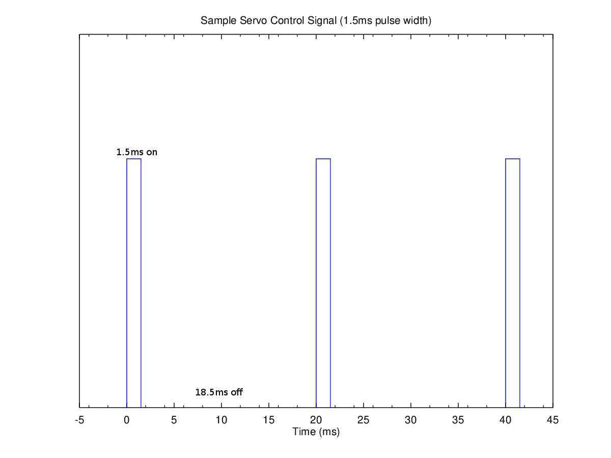
Most hobby servos have a fixed range of rotation, most typically over a range of 0 to 180 degrees. Hobby servos use a single data input signal, and the servo’s angular position is controlled by sending a constant stream of periodic pulses on the input signal. About once every 20ms, a pulse ranging from 1ms to 2ms must be delivered to the servo to cause it to set and hold an angular position. A 1ms pulse every 20ms will rotate a servo to its clockwise limit. A 2ms wide pulse in this window will put it to the opposite limit. A 1.5ms pulse every 20ms will center the servo. The window width has some tolerance, but the width of the pulse will always control the servo’s angle.
Output Compare
Most microcontroller systems offer peripheral timer circuits that can be used to drive periodic signals. The timer circuit function that creates waveform outputs is typically referred to as an “output compare” feature, because an output waveform is generated based on comparing a timer value to the user-programmed values that control the waveform. The Zynq’s TTC module has a waveform generation feature that is essentially an output compare system. The TTC can be configured to drive an output waveform signal high when a certain count value is reached, and then back low when a second compare point is reached. Refer to the backgroud topics and timer reference manual page to learn more about motors, motor control systems, and using the TTC to create appropriate waveforms.
Requirements
1. Center the Servomotor
Configure TTC0 to generate a PWM waveform to center a servo motor. The waveform should drive the servo signal high once every 20ms, leave the signal high for 1.5ms, and then drive the signal low for the remainder of the period (18.5ms). If the servo is not centered when it is connected, it will center itself. if it is centered, it will resist attempts to move it from its centered position.
Before connecting the servo, you can/should examine the PWM signal with an oscilloscope to verify it is correct (or, some multimeters can measure frequency and duty cycle as well - you should verify a frequency of 50Hz and a duty cycle of 7.5% high).
2. Move the servo back and forth over its full range
Rotate the servo continuously from its minimum angle to its maximum angle and back, taking about 5 seconds to go from one extreme to the other. Note that if you simply change the pulse length from 1ms to 2ms (i.e., change the control from “all the way left” to “all the way right”), the servo will rotate from one side to the other at it’s maximum speed, which is much faster than 5 seconds. You need to control the speed of servo by creating pulses that go from 1ms to 2ms over the 5 second interval.
One way to address the problem is to periodically change the angle of the servo. Since a new servo-control pulse must be generated every 20ms (50Hz), there will be 250 servo-control pulses in the 5 second rotation interval. Therefore, if you change between a 1ms and a 2ms pulse in steps of 4us (1ms / 250 is 4us), you will fully rotate the servo over 5 seconds.
You can setup TTC0 to not only create the required output waveform, but to also generate interrupts at the same 20ms (50Hz) interval that is used to define the PWM waveform. Then, when the interrupt occurs, you can change the pulse length by a set amount. Some math will required to calculate how much to modify the match value (find the correlation between the match value and pulse width, and then change the match value by a small fixed amount at each interrupt).
3. Control the servo from a terminal window
Use a terminal window to send servo-postioning commands to control the servo. Move the servo clockwise a small amount with one command, and move it counter-clockwise with another.
4. Add more commands to the terminal interface
Add functionality to your terminal UART controller by letting an user set the absolute position of the servo and the rotation speed of the servo. To set the position (rotaton angle), you could send a number in some fixed range (say 0 to 100) with 0 being the servo’s minimum angle, 50 being centered, and 100 being at it’s maximum angle (or if you know the range of motion of your servo, you can send an angle in degrees instead). To set the speed, you could simply send a number to choose from a number of predetermined speeds (maybe five or ten). ::::
Challenges
1. Read the on-board ADC, and position the servo based on the ADCs value
Assume you are making an older-style, analog-like voltmeter. A “needle” can be attached to a stationary servo held in place by a servo stand, and the assembly can be placed infront of a laser-printed voltmeter graphic. An example of how this may look is shown.
Write a program that changes the servo angle based on the position of the on-board potentiometer that is connected ZYNQ’s on-board ADC. When the potentiometer is at its max value, have the servo go to its maximum angle. When the pot is at its minimum value have the servo set to its minimum angle. Make sure the servo goes to in-between values as well.
To access the ADC, you must first write a “3” to the XADC control regsiter 0 (at offset 0x0300) to connect the ADC input to the VP input pin, and then you can simply read the VP input. See the XADC reference page for more information.
