Creating combined hardware projects for the ARM and FPGA
How to instantiate ZYNQ's ARM processor and add custom IP

Step 1: Tools installation
If you haven’t already installed the Xilinx Vivado and SDK tools, you can follow this tutorial.
Step 2: Create a Vivado Project
Create an empty project in using the latest version of Vivado. Make sure that you select the correct FPGA part for the Blackboard’s Zynq chip. If you need some guidance, you can follow this tutorial.
Step 3: Prepare the Hardware Design
You are now ready to create a block design for your system. This involves creating, adding, and editing a Zynq Processing System as well a custom AXI4 IPcore. Follow this tutorial to prepare the hardware design (make sure to follow all the steps!).
Step 4: Synthesize, Implementation, and Generate Bitstream
After the hardware system is defined, it can be synthesized and implemented. Follow the steps in this tutorial to generate bitstream for your Vivado Project.
Step 5: Design Software using Xilinx Vitis
Export Hardware
To design ARM software that can communicate with your custom AXI IP, you need to export the hardware design for use in Vitis. The hardware design can be imported into Vitis as a .xsa file which tells the IDE about the memory address space of the processor, specifically how axi-bus slaves are mapped into the address space.
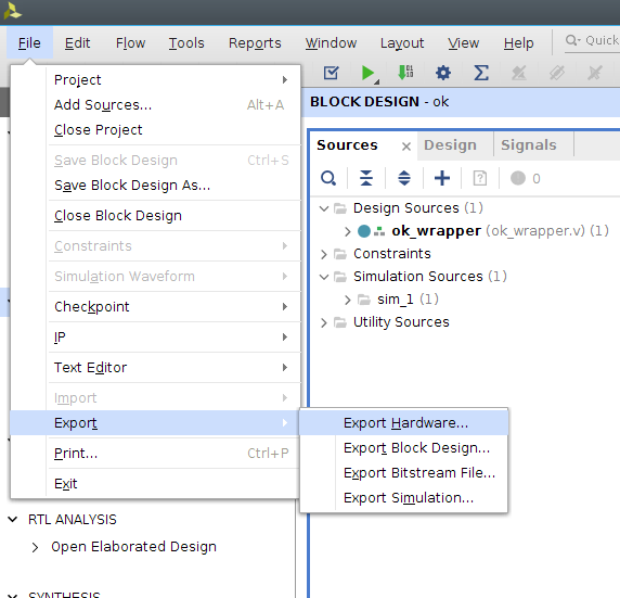
To export a hardware description file, open File Menu, select Export Hardware item under Export.
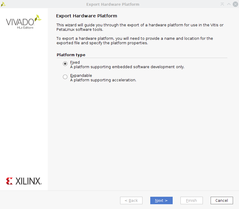
You will be asked to select a platform type. Select ‘Fixed’ here and click next.
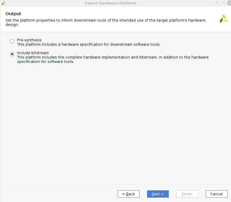
Next, you will be asked which kind of output to create. Select the option to include the bitstream in the exported platform. Continue on to the next dialogue.
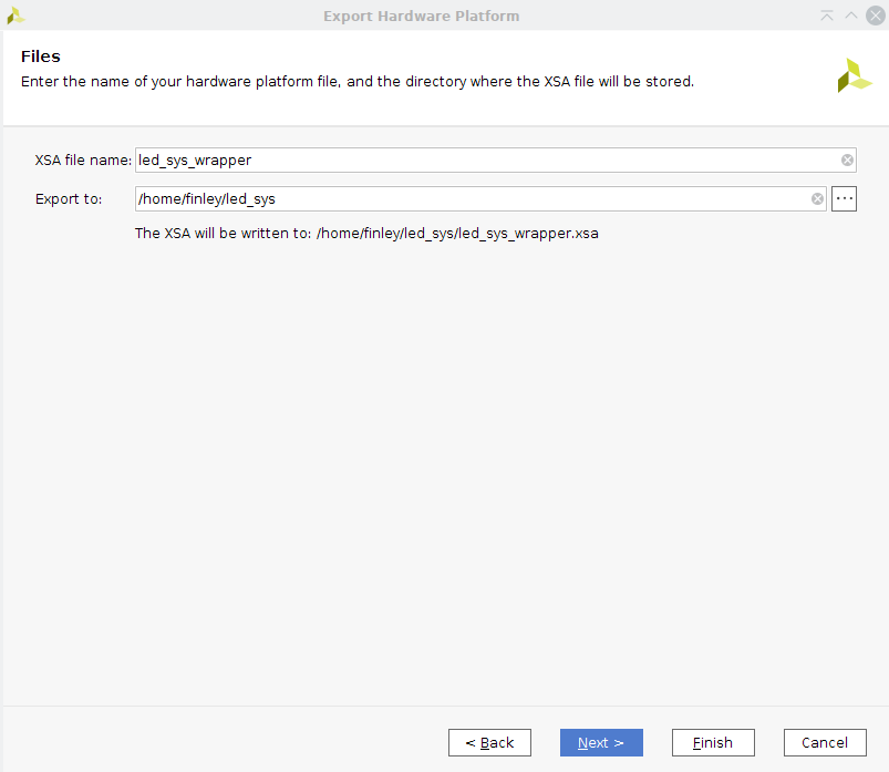
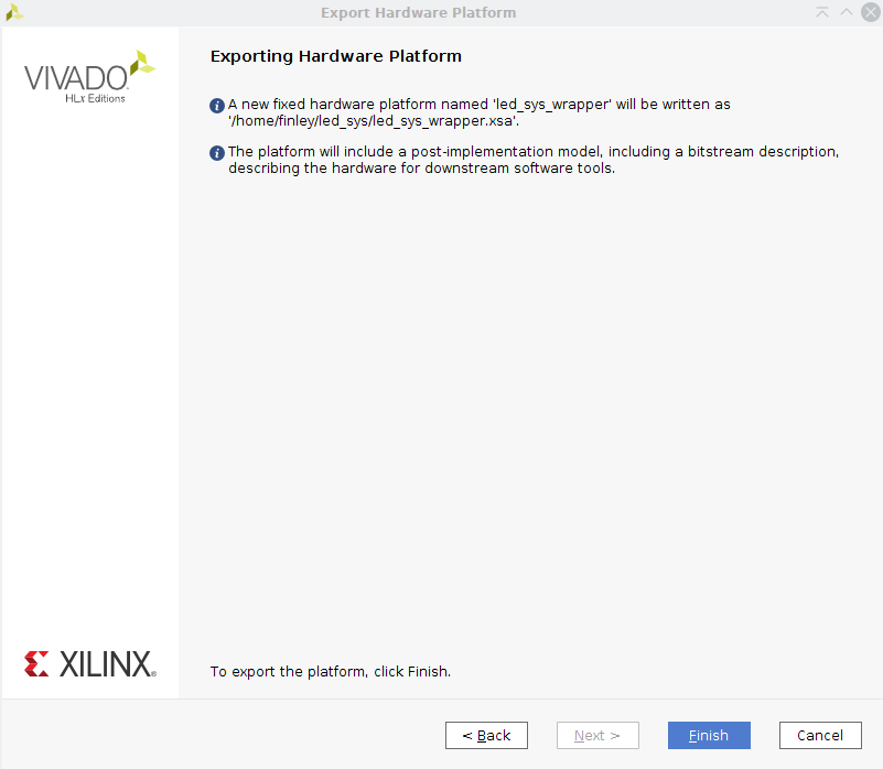
Now you can enter the output file name and export location. By default the export location is within the Vivado project directory. You can leave the default path or place it somewhere else. Make sure you remember where you saved the file as you will need it when importing the platform into Vitis
The final dialogue lets you review the settings and path you selected. Finishing the wizard will write the output xsa to the displayed location.
Launch Vitis and Import Hardware Platform
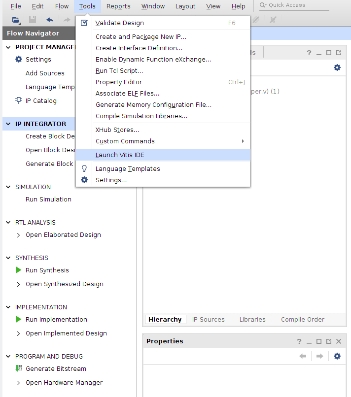
To write a c program for controlling your new LED axi IP, open the Vitis software IDE. This can be done through your system or in Vivado under the ‘tools’ menu tab.
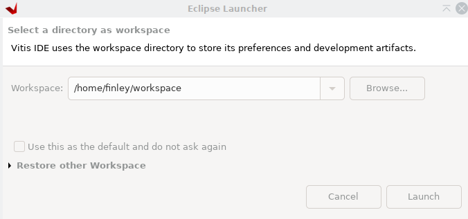
If this is your first time launching Vitis, you will be prompted to open a workspace. Even if you have previously created a workspace, it is recommended you create a new workspace for each hardware platform you develop.
Create a Platform Project The Exported Hardware Platform
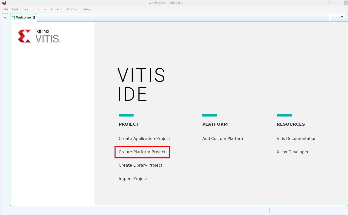
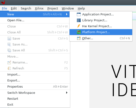
The first time you open vitis, you will see the ‘welcome’ screen. Here you can select “Create Platform Project” to import your custom hardware platform.
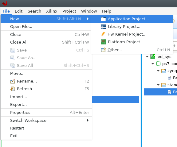
If Vitis doesn’t open to the welcome screen, you can create a platform project from the ‘file’ menu, under the ‘new’ submenu.
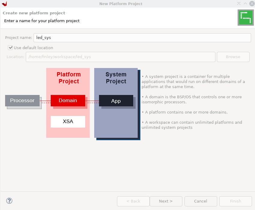
Now the new platform project dialog will appear. Enter a name for the project, then select next.
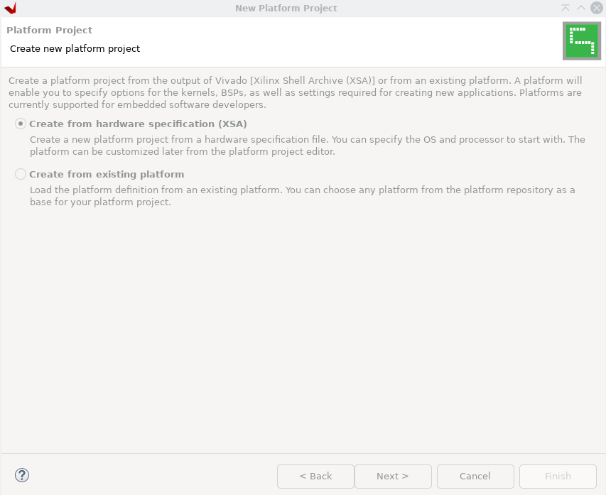
The next screen will ask you the source of the platform description. Select “Create from hardware specification (XSA)” and continue.
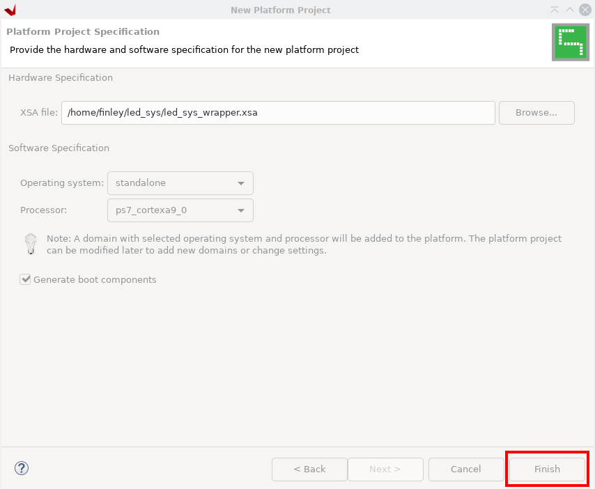
Vitis will now ask you for the location of the exported hardware platform file. Select the file you exported from Vivado and click finish to create the platform project.
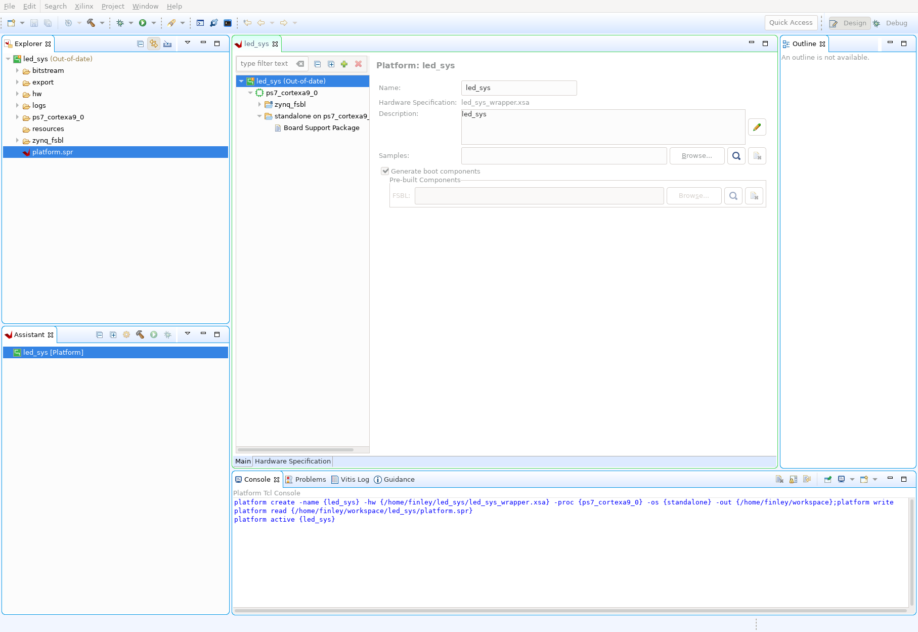
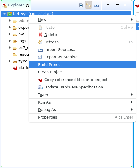
Vitis should now display your imported platform in the main editor window. Additionally, in the project explorer you will see the platform project you just created. There may be a small exclamation point icon above your platform project. If you hover over the icon, Vitis may indicate that the platform is ‘out-of-date’.
By right clicking on the project in the explorer, you can select ‘Build Project’ in the drop-down menu. Vitis will now compile the platform project. Once the build succeeds, the out-of-date warning should disappear.
Creating an Application Project
Now you can add a project for your program. In the ‘file’ menu, under the ‘new’ sub-menu, select “Application Project”.
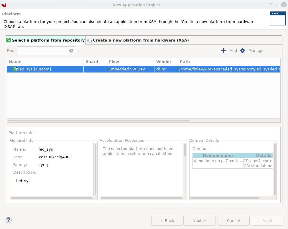
The new project wizard will ask for a hardware platform to use. Select the platform project you created earlier and continue.
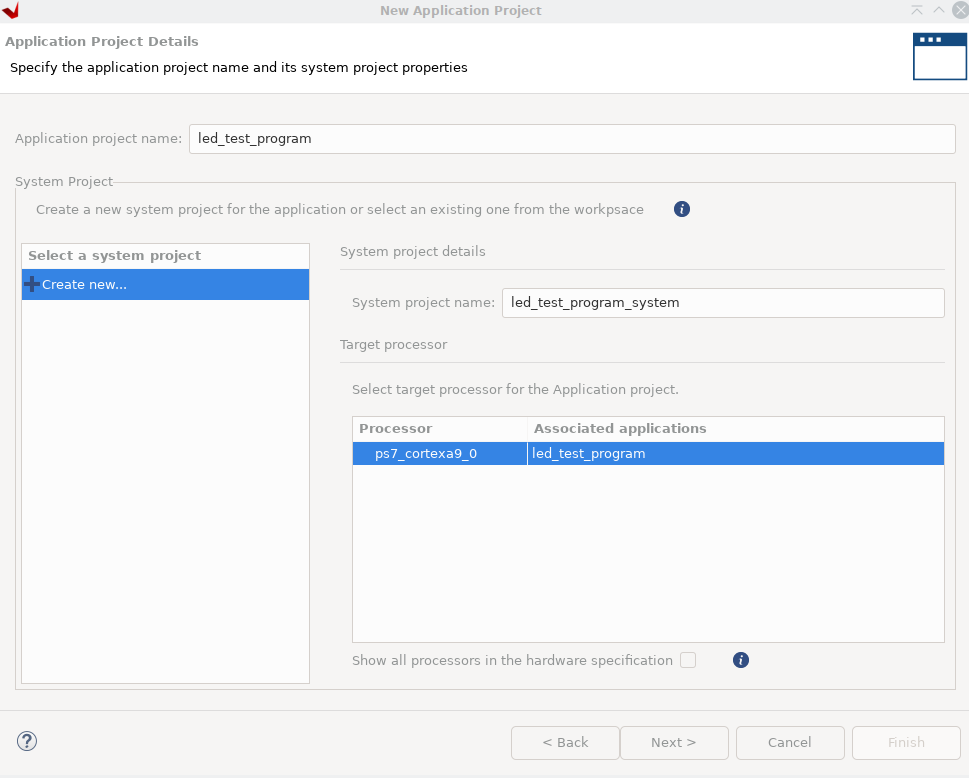
In the next dialogue, enter the name for your project. There is also a place to select a ‘system project’. For your first project you must create a system project, but other projects sharing the same hardware platform can also share the same system project.
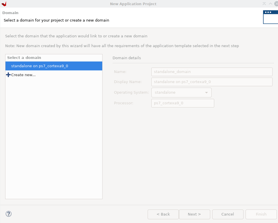
The wizard will now ask for a ‘domain’. Select the only option availible and continue
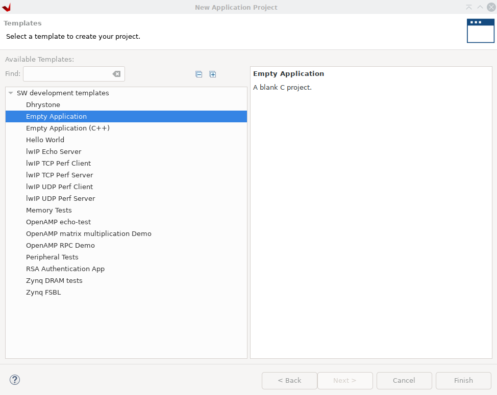
Finally, the wizard will have you select an application template. Choose “Empty Application” and click ‘Finish’ to create the project.
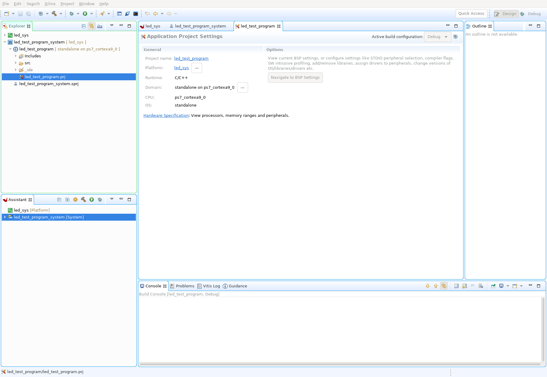
Now your empty Application project will appear in the project explorer
Add a Source File, Write Code, and Compile
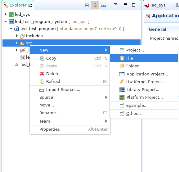
In your newly created project, right click on the ‘src’ directory. In the dropdown menu select ‘new’->‘file’. In the following dialogue enter the name for the source file you want to create. For this tutorial you can create ‘main.c’.
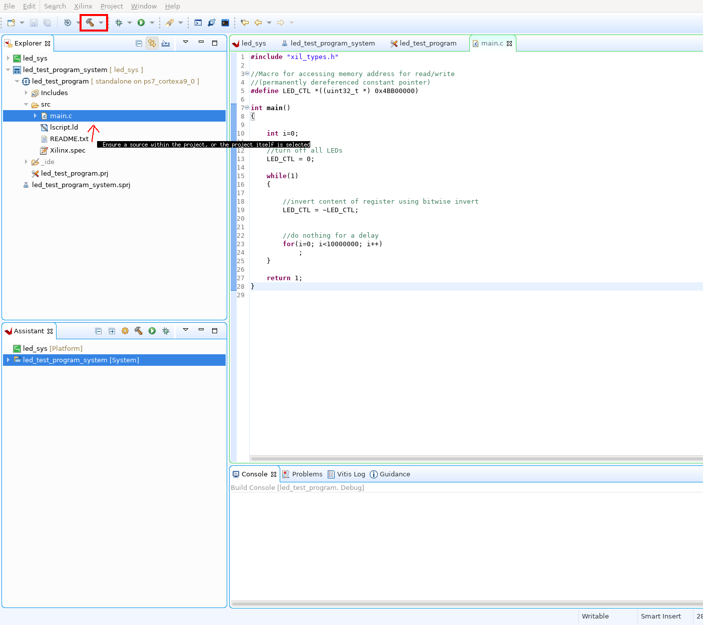
You can now open the source file to edit your program. To test your custom IP core, you can paste the following sample program into your ‘main.c’ file.
#include "xil_types.h"

//Macro for accessing memory address for read/write
//(permanently dereferenced constant pointer)
#define LED_CTL *((uint32_t *) 0x4BB00000)

//test custom LED IP by blinking the lights using software delay
int main()
{

	int i=0;

	//turn off all LEDs
	LED_CTL =0;

	while(1)
	{

		//invert content of register using bitwise invert
		LED_CTL = ~LED_CTL;


		//do nothing for a delay
		for(i=0; i<10000000; i++)
			;
	}

	return 1;
}
Once you have entered your program, you can compile it. Make sure either the application project or a source file within is selected, then click on the ‘Hammer’ icon in the toolbar. You can also right click on a project and build it from the drop-down menu.
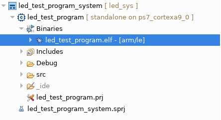
When the application compiles successfully, the binary ‘.elf’ file will appear under your project.
Run Program
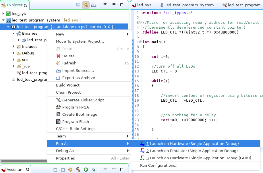
Once you have generated an executable binary, you can run your program on the Blackboard. Right click on your project in the explorer and select ‘Run As’->‘Launch on Hardware’. By default Vitis will attempt to program the FPGA with the bitstream included in the hardware platform. If not follow the steps in the section below to do so manually.
Program FPGA Manually
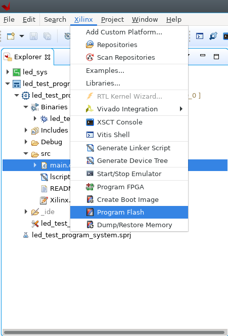
To program the FPGA Manually from Vitis, Select “Program FPGA” from the ‘Xilinx’ Menu.
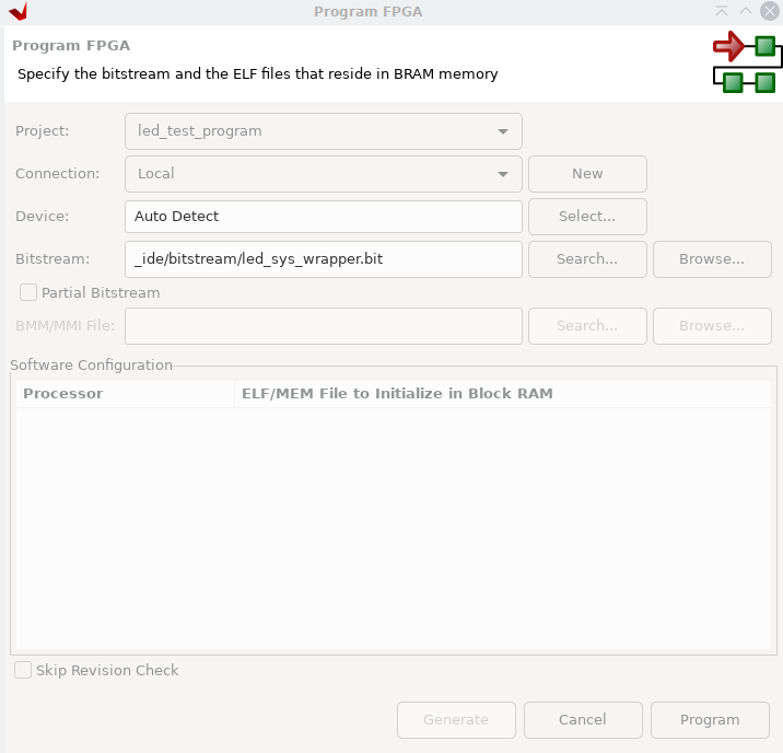
In the Program FPGA dialogue, you can choose a bitstream to program. If the bitstream from the hardware platform you imported is not already selected, add it here. Once a bitstream is selected click ‘Program’ to upload the bitstream and configure the FPGA.
Once you have programmed the FPGA you can run your program on the board, using the steps above.
If you are successful, the provided program will make the LED’s on the board toggle on and off.